poornanop
Newbie level 3
Hi All,
I've got really confused with this...
I've designed a distributed amplifier with following data using N-MOS (L=0.18um and W=10um) :
fc = 12 GHz , Z0= 50
Then simulate the circuit in ADS , It's cut-off frequency works properly but It's Gain is 0 until 12 GHz!
I've attached two pictures :
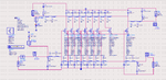
1- The schematic of the circuit in ADS
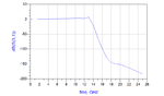
2- The S31 ( means gain, because port 1 is input and port 3 is output)
I've attached the ADS project as well .
Anyone have any experience about distributed amplifier and this problem?
I've got really confused with this...
I've designed a distributed amplifier with following data using N-MOS (L=0.18um and W=10um) :
fc = 12 GHz , Z0= 50
Then simulate the circuit in ADS , It's cut-off frequency works properly but It's Gain is 0 until 12 GHz!
I've attached two pictures :
1- The schematic of the circuit in ADS
2- The S31 ( means gain, because port 1 is input and port 3 is output)
I've attached the ADS project as well .
Anyone have any experience about distributed amplifier and this problem?