Electronics_chaitanya
Member level 5
Hello all
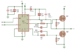
I am making Induction Heater using MOSFETS and IR2110......after reading all information about IR2110 i made circuit....I use SG3525 as oscillator and IR2110 as mosfet driver........
I give 18V as Vcc and 9V for Vdd....output of SG3525 is 8.5V as it divide output=1/2 (input).Input of SG3525 is also 18V
but there was strange problem as i give 8.5V as Vdd but when i place IR2110 in socket Vdd goes to 15.5V and LO output is only about 8V.....
Can anyboady help me to solve problem......
Thanks in advance