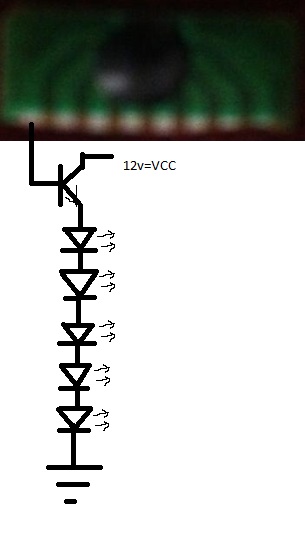
Welcome to our site! EDAboard.com is an international Electronics Discussion Forum focused on EDA software, circuits, schematics, books, theory, papers, asic, pld, 8051, DSP, Network, RF, Analog Design, PCB, Service Manuals... and a whole lot more! To participate you need to register. Registration is free. Click here to register now.
good morning everybody i found this circuit on board of led flasher and i was trying to know the rference but i can't
please can you help me to know it and how it works
all regards
The photo is fuzzy but it looks like a stack of several led's, controlled from a central unit.
A common IC used for this is the 3914 bargraph/dot display driver. It has ten outputs which turn off or on in sequence, based on volt level at the input terminal.
An internet search will provide abundant information about such circuits.
thank you sir for the replly but its not lm3914 bargraph
its a IC that drive 4 leds to be blinked with 4 transistor, 1 capacitor and 2 resistor
all my best regaards
It isn't an IC you could buy in a store, it's a small PCB with an IC mounted on it under the black epoxy. It could be anything, I have a similar one here that flashes four LED chains but what you describe as transistors are SCRs.
yes sir it is using for falshing leds and that's exactly what i need can you help me to know how can i realize it??
because i want to build a small led flasher like that
yes sir it is using for falshing leds and that's exactly what i need can you help me to know how can i realize it??
because i want to build a small led flasher like that
- - - Updated - - -
and can you help me to know the name of this COB??
- - - Updated - - -
yes sir but can you help to know the name or reference for this COB????
The actual working of the COB cannot be determined. The leds may show different patterns. If the chip on COB is a micro-controlller then it is sure that it is programmed to display different patterns. If you want to realize the same circuit using a microcontroller then you can do it easily. Choose any microcontroller with 8 pins for LED and then code can be written to generate different led sequence or patterns.
You mean 5 to 20 connections. Each COM pin can drive only one led or one transistor. You can put 5 leds in parallel at the collector of each transistor and drive the transistor from COB o/p pins. The result is instead on 1 led lighting, 5 leds light up.
i want to driave ecah 5 led with one pin of this COB and the 5 leds will be on series because i want to have the same current on each pin to have a good lighting
Calculate the voltage drop across each led in series. Voltage supplied to transistor circuit should be a little above this. Ic will be the current through each led. Fix Ic to 10 or 15 mA.
The method I gave is for 5 leds in series per tarnsistor. If one led fails then all the 5 leds will be off. You can use any transistor either npn or pnp as it is used as a switching device.
I doubt you will get it to work. The PCR606 is an SCR and the COB is probably producing trigger pulses rather than a continuous signal. In any case, you would want to connect the LEDs in the collector of the transistor because at the momant, to turn the transistor on you have to put (0.6 + total Vf of all the LEDs) volts on it's base and that is almost certainly more than the COB can produce. Try moving the LED's to the colector and adding a resistor, I suggest 2,200 Ohms between the base and the COB output.
Usually, PCR606 is used to drive LEDs which are fed from AC or rectified but not smoothed DC. It relies on the voltage dropping to zero at each half cycle to turn the PCR606 off.
This site uses cookies to help personalise content, tailor your experience and to keep you logged in if you register.
By continuing to use this site, you are consenting to our use of cookies.