Continue to Site

Welcome to EDAboard.com

Welcome to our site! EDAboard.com is an international Electronics Discussion Forum focused on EDA software, circuits, schematics, books, theory, papers, asic, pld, 8051, DSP, Network, RF, Analog Design, PCB, Service Manuals... and a whole lot more! To participate you need to register. Registration is free. Click here to register now.

Designing a power supply(2KW) for a impulse heat sealer

Status
Not open for further replies.

shatruddha

Full Member level 2
Joined
Nov 24, 2009
Messages
141
Helped
19
Reputation
38
Reaction score
19
Trophy points
1,298
Location
india
Activity points
2,177
Hello All
I was working on a project, where I needed to seal a plastic using impulse heating. While doing my calculations, I found that I need a power supply of atleast 1.5kW. So I thought of making a power supply of 2kW, so that if at later stage my power requirements are increased, I wont have to redo the work.
My concern is if I should go for a normal transformer or a switched mode power supply.
If I go with a normal transformer, my disadvantages will be heavy power supply as well as high cost of transformer.
All I can think of is, I do not need an accurately regulated voltage on my output. If I work out for SMPS, I'm confused if I need to use PFC (I read at few links that PFC is kind of redundent for power supplies greater then 1kW, dont know if thats the case though). Secondly will it reduce my cost, as SMPS converts DC signal to high frequency AC, reduce the voltage using a high frequency ferrite transformer and then again convert it to DC. So here is my another question- Do I need to convert this high frequency AC to DC, since my application is Impulse heat sealer, only current does matter to me, no matter if its AC or DC (I'm not sure with this part though).
So from my understanding, all I need is, convert high voltage AC to low voltage AC signal, and I can get desired power for my sealer.
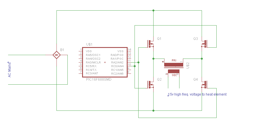
So from my point of view, my design will be fairly simple : rectify the main AC signal (PFC or no PFC still a question)->I get a DC signal here, with ripples though; convert this to high frequency (say 50kHz)-> ferrite core transformer -> low voltage 50kHz (here I think I can feed this signal directly to my impulse heat electrode)
Any inputs in this will be highly appreciated.
Thanks and Regards
Shatruddha
 

If you can specify the resistance or impedance of your heat electrode, then you can determine what voltage you need to apply to dissipate 1.5kW. Most likely you can use triac control AC or cycle count burst control using a ZCS triac with suitable driver.
 

The secret lays within your heater! As you know, 2 KW, can be dissipated in any resistor P= V^2 X R, so until you have firmed up on you heater resistance, the PSU voltage remains a mystery. If you use high frequency AC, then you might have to compensate for the inductance of the heater with a series capacitor.
Frank
 
Last edited:

I'm using a Nichrome electrode as heat element. its dimentions are 330x5x0.5 (mm). So resistance comes out to be 0.132 ohm. So if I give 15v across the electrode; by ohm's law I'll be drawing 15/0.132 = 113.6A. With this much current I will be able to provide a power of 1.7kw.
So if I design my PSU, my major considerations will be choosing a mosfet and high frequency transformer. Can I use a normal high frequency transformer that is used in a 500w SMPS? or Do I need to do any modifications. I'm least idea about this part.

- - - Updated - - -

Hi Sunny
Idea of using Triac is good, but while using a Triac, I will be drawing a huge current for the pulse when my triac is on. For a resistance of 0.132 ohm, current will grow more then 1600A for 220v AC. To reduce the current I was thinking to design PSU and reduce the voltage applied across my electrode and hence current.
Please let me know if I'm wrong at any point or if there is a better alternative for my case.
Thanks
 

I think a 500W transformer is rated at 500W, so you need four of them. One point that has occurred to me is the size of your reservoir capacitor and then the need for a soft start for the rectifiers. A more cost effective way might be, not have a reservoir capacitor and adjust the transformer turns ratio to give the correct RMS power with what will be a sine wave chopped by your switching waveform, which I think means that you need 1.4 X your 15V.
Unless there is an overwhelming requirement for a light unit, I would buy a 2KW mains to 110V isolation transformer for about £50, rip of the 110V windings and wind on the 15V winding - the wire will cost another £50.
Frank
 

If you want to design a low cost heat sealer, then you must use AC power without any conversion. Otherwise you end up with a welder or an expensive SMPS @ $1/W.

To do this you must choose a much thinner heating element with perhaps many windings in series.
 

Hi Chuckey
Even I was thinking on the same track. So basically what I will do is convert the rectified rectified voltage to high frequency (say 40kHz) voltage. So this high frequency voltage signal will follow an envelop of 100Hz, which is no problem to me at all. then I will use a high frequency step down transformer to step down the voltage to say 15V and feed it to my heat element.
Take a look at the rough schematic that I've drawn


Now my major concerns are mosfet selection and high frequency transformer.
I see that I need to use a mosfet with Ids>15A and Vds>=200V which are quite easily available.
For transformer, I was wondering if I can use the ordinary high frequency transformer that is used in 4-500W SMPS. They are ferrite core, all I need to do is rewind it as per my requirement. I've got a few non working SMPS with me, so getting the ferrite will not be a problem.

I can use AC directly to heat my electrode, but since resistance of my electrode is very less (0.1 ohm) it will draw a current in thousands of amps, which I want to avoid.
 

hi
I was playing around with the transformer that I took out from my old SMPS. I see that its E type. Ae ≈ 96 mm² (Dia ≈ 11.1). I've also checked for total winding area available, and that comes out to be 75 mm².
Now when I did my calculations for primary no. of turns N1 using the equation
N1 = V1/(2*f*ΔB*Ae)
here I choose ΔB = 0.4T, which I found was good after a bit of googling.
V1 is 170 Vrms and Ae is 96mm²
for f = 50kHz I got N1 ≈ 45
similarly for f = 100kHz and 200kHz N1 was 23 and 12 respectively.
since N1/N2=V1/V2 so i find my N2 =1;

So far, so good.
Now I calculated Area of cross section of winding wire. using the eqn W = I/J.
I choose current density J = 4.32 A/mm², which I found out after a bit of googling and suitable to use.
So if my primary current goes upto 10A,
W1=10/4.32 ≈ 2.33 mm².
and W2 = 120/4.32 ≈ 27.8 mm²
since these area of cross sections are too large considering skin effect, So I'm thinking to go for parallel strands.
Say I have an insulated copper wire of cross section ≈0.6 mm². I will need 2.33/0.6 = 4 parallel wires for primary and 27.8/0.6 = 47 parallel wire for secondary.
since my winding area is quite less, best frequency that I find suitable for me is 200kHz. in that freq. i will be using 0.6*4*12 = 28.8 mm² for my primary and 0.6*47*1 = 28.2 mm³ for secondary.
Total winding area that I will be using is 57 mm² out of 75 mm². Well and good for me.

Now my question is : is there any flaw in my design?
am I missing something?
 

"I can use AC directly to heat my electrode, but since resistance of my electrode is very less (0.1 ohm) it will draw a current in thousands of amps, which I want to avoid."
Your AC secondary will need to deliver the equivalent of 15v RMS at a current of 100+ Amps. Where did you get thousands from?.
Frank
 

Here are the specifications for a 2KW RF transformer 150A max

2KW xfmr.jpg
Since they are custom, they wont be cheap. Let us know what you find out.,

Compare with a 100F 16V 2 mOhm Ultracap @ $600 and cheap charger..
 

My soldering gun contains a transformer which steps down mains AC to around 1V AC.

The secondary consists of a few turns of very thick copper wire.

The gun is 100W or 200W, so there must be over 100A going through the tip.

The tip can become red hot if I keep it on for half a minute or so.

I imagine a nichrome wire will heat up much more quickly.
 

Hi chuckey,skyguru,Brad
I find the solutions provided by you amazing, I did not think up that way. Working it out your ways will help a lot.
But my major objective here is to learn new things. Now that I've stepped into high frequency things, I would like to work it out that way only. I see that high frequency conversion is used at quite a lot of places like impulse heater, CFL etc.
So I would like to get my hands dirty in that.
I appreciate all the help that you have brought me and will appreciate all further suggestions and help.
Regards
Shatruddha
 

Hi All
Today I received the ETD core and bobbin that I ordered. So I have an ETD44 core with 3c90 material. Effective cross section area is 173 mm² and winding area is 214 mm².
I figured out that I can transfer upto 1500w using it, with proper selection of frequency and duty cycle. I also calculated that primary number of turns = 23 and secondary number of turns = 3. V1 = 220v, V2 = 28v; I1= 7A, I2 = 54A.
accordingly wire diameter d1 = 1.89 mm and d2 = 5.24 mm.
for a frequency of 200khz skin depth comes around 5mm.
Now I need help in verifying my calculations.
Further more is it a good idea to use full bridge inverter or forward inverter?
How to do the winding?, as in should I use a single wire or multiple strands of wires combined together to make a litz wire?
 

HI
I was wrong about skin depth at 200 kHz, its not 5mm its 0.17mm so I think its safe to choose a wire with diameter 0.3mm. Now if I want a litz wire for winding, how many strands of 0.3mm should be there for conduction of 54A? I'm not able to figure it out.
 

Status
Not open for further replies.

Part and Inventory Search

Welcome to EDABoard.com

Sponsor

Back
Top