Continue to Site
Follow along with the video below to see how to install our site as a web app on your home screen.
Note: This feature may not be available in some browsers.
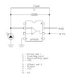
LM741 with 320M feedback resistor will be in no sense OK.Will the selected op amp in the below circuit be OK?
analog-designer said:The Photodiode need to be biased in reverse operation mode