Continue to Site

Welcome to EDAboard.com

Welcome to our site! EDAboard.com is an international Electronics Discussion Forum focused on EDA software, circuits, schematics, books, theory, papers, asic, pld, 8051, DSP, Network, RF, Analog Design, PCB, Service Manuals... and a whole lot more! To participate you need to register. Registration is free. Click here to register now.

discrete buck converter with Ltspice from linear technology

Status
Not open for further replies.

yassin.kraouch

Advanced Member level 2
Joined
Jul 5, 2009
Messages
631
Helped
40
Reputation
80
Reaction score
40
Trophy points
1,308
Activity points
5,094
Hi,
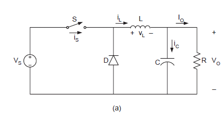
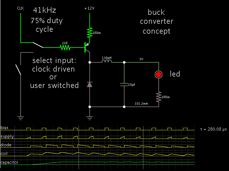
can you please help me to simulate this circuit ? and explain it to me,
i tried to use LT spice to simulate the circuit, but every time i failed to do that to edaboard.png
 

Hi!
L1 is small.
 

Attachments

  • buck.zip
    893 bytes · Views: 73

Hi Pplus, thank you for your reply, but when i tried to simulate the circuit, he said can't find BC547A, can you please help me on this ?
 

Change on other npn - 2n222 as example, or use another library.
 

Attachments

  • Standard.zip
    123.4 KB · Views: 55

can you please help me to understand this circuit ? and also how to add this transistor on ltspice ?
thanks
 

Unpack Standard.zip on ?\Program Files\LTC\LTspiceIV\lib\cmp and restart LTspice.
 

yes but i have still the problem with LED, can't find the model.
can you please explain to me the schematic ?
 

Change on other LED or simple diode.
 

Ok, can you please explain to me how the schematic works ?
i am confused the current curve is not so good, see pictureto edaboardddd.png
 

In my simulation seems good
4832681700_1368534775.png

3101426900_1368534900.png


**broken link removed**
 

really i don't understand why i have this result,
can you please explain to me the schematic ?

- - - Updated - - -

can you please reply to my answer ? i need it asap, it's urgent,
thanks
 

I hope that you know how work the buck converter.
3795891300_1368601867.png

S is IRF9540, L-L1, D-D2, C-C1, R-D1 on your drawing. It remains to determine what controls the key S.
R1 is current sensor for R(D1). If U(R1)> 0.65V -> Q2 turn on, Q1 and IRF9540 turn off. After some time, determined by the energy stored in the inductance L current through R1 begins to decrease. If U(R1)< 0.65V -> Q2 turn off, Q1 and IRF9540 turn on, current through R1 begins to increase, the process is repeated.
Note that the circuit is very sensitive to the parameters of inductance L1. For it small values ​ or low quality of the generation breaks down and scheme degenerates into a linear current regulator.
 

Here is my simulation of a basic buck converter, showing waveforms.


The coil is at the heart of the action. It will help if you put a scope trace on it, to show the current through it.

The duty cycle is determined by the proportion of output V to supply V. (I guessed 3V for the led, 12V for the supply.)

The operating frequency is largely determined by the coil's value (130uH in your schematic).

I determined the frequency by clicking the switch to turn on the transistor. I tried to maintain 300 mA through the high-brightness led. Eventually I found a constant tempo. The scope trace showed 41 kHz or so.

Notice how the waveforms soar for a few cycles after startup. Then they settle down at an even pattern.

To get a grasp on the concept of operation, it helps to have an interactive animated simulation (I used Falstad's). Click the link below to open the website falstad.com/circuit, load my schematic in his simulator, and run it on your computer.

https://tinyurl.com/a4petgt
 

Status
Not open for further replies.

Similar threads

Part and Inventory Search

Welcome to EDABoard.com

Sponsor

Back
Top