Continue to Site

Welcome to EDAboard.com

Welcome to our site! EDAboard.com is an international Electronics Discussion Forum focused on EDA software, circuits, schematics, books, theory, papers, asic, pld, 8051, DSP, Network, RF, Analog Design, PCB, Service Manuals... and a whole lot more! To participate you need to register. Registration is free. Click here to register now.

Pic Controlled Relay Timer

Status
Not open for further replies.

GranTotem

Newbie level 5
Joined
Nov 8, 2011
Messages
9
Helped
0
Reputation
0
Reaction score
0
Trophy points
1,281
Activity points
1,383
Hello everyone,

I have a heater at home which I want to turn on every day at 6pm for 30 minutes.

I am planning on using a PIC16f684 to control a 20A relay to turn it on.

Now my question is: Should I use an RTC (DS1307) to tell time or create a very long delay in the program (If possible)?

There would be a couple status LEDs and Buttons as well...

Thanks in advance,

GranTotem
 

I'd go with an RTC, much more stable. Then you don't have to analyze & compensate for the long-term clock error accumulations, which will cause your delay counters to drift away from 6PM... either longer or shorter. The RTC will be much more accurate over a long period of time (days/weeks/months).
 

definitely you go with RTC, it will have more accuracy than your timer(delay).
go ahead with DS1307.
 

Hi,

Or just use the 32khz watch crystal on Timer1 pins and write your own rtc routine - used it like that for years.

See the 16f88 datasheet Timer1 section for full details of a RTC.


One problem you may have with such a heavy heater load is that the relays switching may cause the Pic program to fail or reset intermittantly.
Have found a Zero Cross Over SSR removes this problem, though not cheap at 20A, but seems like some good prices on ebay.
 

Microchip Real-Time Clock/Calendar
**broken link removed**

MCP79412
**broken link removed**

See example codes and rest informations.


A 16F88 PIC Based Clock and Calendar using a Dallas DS1307 RTC Device for battery backed up timekeeping
**broken link removed**

**broken link removed**

http://www.best-microcontroller-projects.com/real-time-clock-ic.html

real-time-clock-ic-block-diag.png
 
  • Like
Reactions: FvM

    FvM

    Points: 2
    Helpful Answer Positive Rating
One problem you may have with such a heavy heater load is that the relays switching may cause the Pic program to fail or reset intermittantly.

How can we avoid controller rest with relay.

I have developed a system something like this but for different application. I'm facing controller reset prob. during relay ON and OFF. What and all we can do for avoiding controller reset. I'm using PIC16F877A controller.
 

Thread owner mentioned heater and 20A, I suppose its on mains voltage 220V/110V, relay in any way cant affect on PIC. PIC should have good and correctly designed power supply with 100nF close to supply pins of uC, relay should have flyback diode around coil. Relay coil can be on the same voltage which supply uC or can be on any other different voltage.

As additional to case, I think this is not a job for relay, you need to use contactor not relay. If you use contactor with coil on 220V then use small low voltage relay to drive coil of contactor.
 
Last edited:
  • Like
Reactions: FvM

    FvM

    Points: 2
    Helpful Answer Positive Rating
The OP mentioned 20A relay. uC should have independent supply from the rest of the circuit and it's outputs should be galvanicaly isolated (not even having common ground).
Hunting for sources that can cause the uC reset can take a loooooooong time, if you do not have some experience.
 

So to sum it all up,

RTC definitely, I have decided to move to a PIC16f877 to have a display telling me the current time, time at witch relay is triggered and for how long.

So about the relay,

"tpetar" mentioned I should use a contactor, could you explain to me the concept of the contactor because I am not sure I fully understand how to use it.

And "wp100" mentioned that the PIC might reset itself due to high load. If I use a contactor, will I solve the issue? Besides, if it is intermittent, assuming its a couple milliseconds, wouldn't a big capacitor solve the problem? (Could have the display normally off so that the current draw is lower)
 

Contactor is stronger then relay, with stronger construction to switch higher currents. Avoid usage of relays for higher currents, specially on longer period.
 
  • Like
Reactions: FvM

    FvM

    Points: 2
    Helpful Answer Positive Rating
So basically a more powerful relay.
What about the relay you said I should use to drive the contactor? Can't I just drive the contactor like I would a relay using a transistor connected to the uC?
 

Yes, small relay drive contactor coil. Contactor can have 220V/110V coil this will be problem for transistor.
 
  • Like
Reactions: FvM

    FvM

    Points: 2
    Helpful Answer Positive Rating
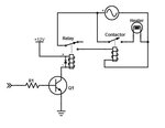
it's something like this.

Drive contactor.JPG

Q1 transistor will drive relay. Relay will drive contactor. Heater will be driven thru the contactor.
 

Clock Controller V2.0
preset set time on/off


**broken link removed**
 

Clock Controller V2.0
preset set time on/off


**broken link removed**


Yes, this clock works nice, I build few timer clock devices for thermo accumulation oven for my friends, and all works for long time without single problem. On this link you can find my PCB but, it can be drastically smaller in SMD on double sided PC, I didnt have in that time 89C2051 in SMD and I use DIP version. In my photo album you can find pictures of finished device.
 
Last edited:
  • Like
Reactions: FvM

    FvM

    Points: 2
    Helpful Answer Positive Rating
Yes, I like the schematic of the "Clock Controller" and I now understand how to use the contactor.
I have been thinking about it and I might even go with servo on a mount, which flips the switch on the wall, this would make the solution more portable and cheaper being able to use it to control anything that has a switch and since I have to do this for 3 heaters... I might go for this one (They are all turned on through a switch on the wall).

Thanks!
 

Status
Not open for further replies.

Similar threads

Part and Inventory Search

Welcome to EDABoard.com

Sponsor

Back
Top