ilacmano
Newbie level 6
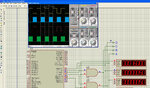
I have used the Fast PWM mode for generating SPWM 16 kHz signal with microcontroller
ATMEGA16 wth oscillator frequency 16Mhz (see Atmega16 50Hz sine wave.jpg). Program written in Bascom AVR.
Our frequency is 50Hz – time period is 20ms. A half cycle takes 10ms. Recall that the
sine table used is only for half a cycle. So, the 32 values must be called such that they
make up the half cycle.
The SPWM generation is done by the single PWM module and which IR2112 to send the signals
to is set by the "Direction" bit and the hardware trick employing the AND gates. When
"Direction" is equal to 0, the high side IR2110-1 A is kept on for 10ms during which time
the SPWM signals on PWM (OC1A) output (PORTD5) are sent to low side IR2112-1 D by sending
a "1" to PORTD3, which, with the help of the AND gate "diverts" the OC1A signal to the
low side IR2112-1 D (see Atmega16 50Hz sine wave.jpg). The same thing is achieved when
"Direction" is equal to 1, just with high side IR2112-2 C and low side IR2112-2 B. When
IR2112-1 A and D are operated, IR2112-2 B and C are kept off and vice versa. For IR2112
drive, we need 4 pins for the 4 drive signals and I’ve chosen PORTD bits 0 to 3. I’ve
arbitrarily chosen these four pins but you can choose any four pins really. The IR2112
are first turned off before the other two are turned on, as can be seen in the code
block:
if Direction = 0 Then
MOSA = Reset 'A=0
MOSD = Reset 'D=0
MOSB = Set 'B=1
MOSC = Set 'C=1
Direction = 1
else
MOSB = Reset 'B=0
MOSC = Reset 'C=0
MOSA = Set 'A=1
MOSD = Set 'D=1
Direction = 0
End IF
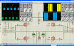
For Full Bridge IGBT drivers I'm use IR2112 (because don't found IR2110 model)in simulation in Proteus Isis with IRG4PC50KD (see IR2112-IRG4PC50KD-Inverter.jpg).
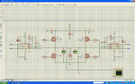
Have problem on output have signal is 290VDC not 220VAC 50Hz (see IR2112-IRG4PC50KD-Inverter-1.jpg).
I do not know to what I'm doing wrong.
ATMEGA16 wth oscillator frequency 16Mhz (see Atmega16 50Hz sine wave.jpg). Program written in Bascom AVR.
Our frequency is 50Hz – time period is 20ms. A half cycle takes 10ms. Recall that the
sine table used is only for half a cycle. So, the 32 values must be called such that they
make up the half cycle.
The SPWM generation is done by the single PWM module and which IR2112 to send the signals
to is set by the "Direction" bit and the hardware trick employing the AND gates. When
"Direction" is equal to 0, the high side IR2110-1 A is kept on for 10ms during which time
the SPWM signals on PWM (OC1A) output (PORTD5) are sent to low side IR2112-1 D by sending
a "1" to PORTD3, which, with the help of the AND gate "diverts" the OC1A signal to the
low side IR2112-1 D (see Atmega16 50Hz sine wave.jpg). The same thing is achieved when
"Direction" is equal to 1, just with high side IR2112-2 C and low side IR2112-2 B. When
IR2112-1 A and D are operated, IR2112-2 B and C are kept off and vice versa. For IR2112
drive, we need 4 pins for the 4 drive signals and I’ve chosen PORTD bits 0 to 3. I’ve
arbitrarily chosen these four pins but you can choose any four pins really. The IR2112
are first turned off before the other two are turned on, as can be seen in the code
block:
if Direction = 0 Then
MOSA = Reset 'A=0
MOSD = Reset 'D=0
MOSB = Set 'B=1
MOSC = Set 'C=1
Direction = 1
else
MOSB = Reset 'B=0
MOSC = Reset 'C=0
MOSA = Set 'A=1
MOSD = Set 'D=1
Direction = 0
End IF
For Full Bridge IGBT drivers I'm use IR2112 (because don't found IR2110 model)in simulation in Proteus Isis with IRG4PC50KD (see IR2112-IRG4PC50KD-Inverter.jpg).
Have problem on output have signal is 290VDC not 220VAC 50Hz (see IR2112-IRG4PC50KD-Inverter-1.jpg).
I do not know to what I'm doing wrong.