Continue to Site

Welcome to EDAboard.com

Welcome to our site! EDAboard.com is an international Electronics Discussion Forum focused on EDA software, circuits, schematics, books, theory, papers, asic, pld, 8051, DSP, Network, RF, Analog Design, PCB, Service Manuals... and a whole lot more! To participate you need to register. Registration is free. Click here to register now.

Mosfet switch for switching between two power supplies

Status
Not open for further replies.

MILIND42

Newbie level 6
Joined
Apr 3, 2013
Messages
14
Helped
0
Reputation
0
Reaction score
0
Trophy points
1,281
Activity points
1,373
Hi
I have a 5 volt supply and a 3.3 volt supply and i need a switch which can choose between those 2 supplies and give an output which is either 5v or 3.3 v.i want to have a mosfet switch.can anyone tell me which mosfet to use and is my circuit correct?

5V
o------------------(mosfet)-----------


3V
o-------(diode (|>|))------------------

There is a connection between the two ends and an external control is there attached to mosfet
 
Last edited:

This will work in theory, if you apply sufficient gate voltage to the mosfet.

However the diode will subtract 0.6V from your 3V (or 3.3 V) supply.
 
This will work in theory, if you apply sufficient gate voltage to the mosfet.

However the diode will subtract 0.6V from your 3V (or 3.3 V) supply.

you have to use a pmos otherwise after switch you will have either 5-vth or 3-vth . now whenever you connect the gate to 5 volt (in order to turn the pmos off) the pmos will not turn off, it will be diode connected(gate and source are connected to 5volt while drain is at 3volts) therefore a static current and static power consumption would be present in your circuit. also note that your voltage source won't be an ideal voltage source since the resistance of the swith or diode is always on your circuit's path. the speed of your circuit may degrade too. then you should use wider transistor and diode which means more static power.
 

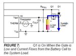
see the circuit. It may give you an idea.
 

Attachments

  • loadSharingCircuit.JPG
    loadSharingCircuit.JPG
    42.1 KB · Views: 404
  • Q1_Source_Drain.jpg
    Q1_Source_Drain.jpg
    15.8 KB · Views: 398
Hi Mahdi
Thanx for ur reply

I was wondering that why my pmos switch wont turn off if i apply 5 volts to the gate.I am planning to have 5v at (source + gate) side and 3.3 v on drain side.now whenever i ll give 5v to gate the switch ll remain off and the output ll be 3.3 volts.do u think it ll work?

- - - Updated - - -

Hi speedEC

Do i need to have my second input(3.3v) on drain side and my first input(5v) on source side?

Regards
milind
 

Do i need to have my second input(3.3v) on drain side and my first input(5v) on source side?

Correct. You can do test and confirm yourself. If +5v available, this will drive the P-CH MOSFET GATE (high) and cut-off the 3.3v supply and +5v ( - diode voltage drop) to system load. If +5v not available (this is by default - switch (p ch mosfet) closed because of grounded gate through 100K resistor), 3.3v supplies to system load.
 
Last edited:

sorry I've made a mistake the pmos will turn off. but as I said the resistance of your voltage source is no longer negligible. this can sometimes be problematic.
 

If +5v available, this will drive the P-CH MOSFET GATE (high) and cut-off the 3.3v supply and +5v ( - diode voltage drop) to system load. If +5v not available (this is by default - switch (p ch mosfet) closed because of grounded gate through 100K resistor), 3.3v supplies to system load.

Hi SpeedEC

As it is a pmos switch,whenever the gate voltage is high the switch ll turn off right and vice versa.so as my circuit is like this


5v o------------------{S--D}-----(output)----|<|--------o 3.3v

control.......................G

5Vs ll be the output when switch is on(i.e low gate voltage) and (3.3 V- diode voltage) ll be the output when switch is off(i.e high gate voltage)?
 

Pl post circuit diagram instead of plain text. It will be easy for anyone to give correct answer.

Note: see my circuit and test yourself using simple p-ch mos(available locally) on circuit.
 

Hi SpeedEC

As it is a pmos switch,whenever the gate voltage is high the switch ll turn off right and vice versa.so as my circuit is like this


5v o------------------{S--D}-----(output)----|<|--------o 3.3v

control.......................G

5Vs ll be the output when switch is on(i.e low gate voltage) and (3.3 V- diode voltage) ll be the output when switch is off(i.e high gate voltage)?

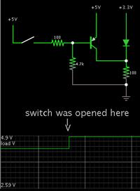
Here is a schematic using Falstad's animated simulator. (I substituted a transistor for a P-mosfet because the mosfet model does not always turn on sufficiently.)


When the transistor is turned on, the load gets 5V (nearly).

At other times, it is 2.59V ( 3.3 minus the diode drop).
 

is this the result you want actually? Right?
 

    V

    Points: 2
    Helpful Answer Positive Rating
Status
Not open for further replies.

Part and Inventory Search

Welcome to EDABoard.com

Sponsor

Back
Top