Continue to Site

Welcome to EDAboard.com

Welcome to our site! EDAboard.com is an international Electronics Discussion Forum focused on EDA software, circuits, schematics, books, theory, papers, asic, pld, 8051, DSP, Network, RF, Analog Design, PCB, Service Manuals... and a whole lot more! To participate you need to register. Registration is free. Click here to register now.

My solution for mapping up to 64 touch 'piano' keys to 6 Arduino analog pins

Status
Not open for further replies.

boylesg

Advanced Member level 4
Joined
Jul 15, 2012
Messages
1,023
Helped
5
Reputation
10
Reaction score
6
Trophy points
1,318
Location
Epping, Victoria, Australia
Activity points
11,697
I have printed piano keyboard which I will stick on to a sheet of MBF.

Two nails will be hammered through each key to create electrical contacts to which I can connect wires to below.

Each of these will have a one transistor 'touch' amplifer and the output of these will feed into one or more contacts, on 'Keyboard' header in the circuit below.

The resulting pattern of voltages on the arduino anaolg pins will be read as a binary number between 1 and 64 which will in turn be mapped to the frequency and tone corresponding to that piano key.

If I can control the voltage levels well enough I could potentially have two sets of 64 keys = 128 possible piano keys. E.G. One set of 64 keys that read in as a 5V logic level on the analog pins and another set of 64 keys that read in as a 9V level on the analog pins.

The fun part will be in the arduino programing, sorting out simultaneous 'presses' of more than one piano key at a time which would result in a 'hybrid' signal on the analog pins.

I also want to try and do the analog pin reading via interrupt rather polling, but I am not yet all that clear on how you setup and handle interrupts in an arduino sketch yet.

Any comments or suggestions for improvement?
 

Your design could work.
As you say, it will require careful measuring and programming to distinguish the various volt levels.

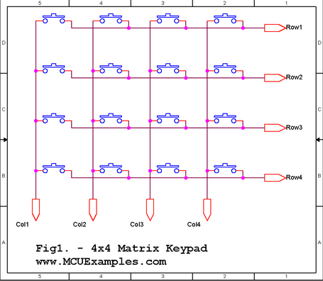
Did you rule out the common keypad matrix?

3157302400_1368067746.png


The above was found at:


I suppose you would need 8 rows by 8 columns to read a 64 switch keyboard. That means you need 16 inputs on the Arduino. Might not be feasible.

Is that how PC keyboards work is it? Always wondered about that.

I have the Freetronics Eleven which is almost the same as the Uno with 14 digital pins.

I need two of those for the sine wave output leaving me 12 pins and giving me 6 x 6 = 36 possible piano keys.

Compared to up to 60, using a single voltage level, with my method.
 

I think you might run into problems with analog measurements, especially with voltage drift caused by changing temperature.

I would go with the 'expander' solution. Use one pin to reset a Johnson counter (CD4017?), another to clock it, that gives you 10 sequenced drive signals to the keys and 4 inputs still unsed to read the keys back so even if you use them as they are, you have 40 keys already. If you use a diode matrix (or better still, a binary encoder IC) to encode the return signals back to four bits you can read 160 (16 x 10) keys back. The advantage of doing it digitally is your software can look for more than one key being pressed. If you do it using analog methods and press more than one key, the resulting voltage will not represent the two notes you pressed but a single other note.

Yes, that is how PC keyboards work, in fact how almost all keyboards and keypads work. In a PC, the keyboard has it's own processor that scans the keys and converts the key number into a code which is sent serially to the motherboard. Similarly, it receives serial commands to turn the indicator LEDs on and off.

Brian.

I could see that I might run into problems if I was trying to use two different voltage levels for two different sets of 64 piano keys but for a single set where I just have to detect a voltage level above 1 or 2V then I reckon it should be fairly robust.

I have tested this with a real circuit connected to my arduino, and the voltage levels induced on its analog pins were consistently 2V or more while the LOW pins were consistently less than 0.5V.

If I was to pursue the two voltage levels idea then I may have to bump up the voltage to 9V or so to provide more 'room' between the drifts around each voltage level.


Status
Not open for further replies.

Similar threads

Part and Inventory Search

Welcome to EDABoard.com

Sponsor

Back
Top