Continue to Site

Welcome to EDAboard.com

Welcome to our site! EDAboard.com is an international Electronics Discussion Forum focused on EDA software, circuits, schematics, books, theory, papers, asic, pld, 8051, DSP, Network, RF, Analog Design, PCB, Service Manuals... and a whole lot more! To participate you need to register. Registration is free. Click here to register now.

how to run MIPS multi-cycle processor on Xilinx Spartan 6 fpga

Status
Not open for further replies.

comp_engineer

Newbie level 5
Joined
Mar 23, 2013
Messages
10
Helped
0
Reputation
0
Reaction score
0
Trophy points
1,281
Activity points
1,385
hello everyone

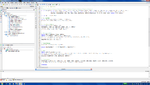
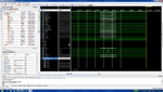
So I wrote a Multi-Cycle Processor from scratch in Verilog HDL(I've tested it and it is indeed working fine), and I have purchased a Xilinx Spartan 6 FPGA (50mhz), and i'd like to implement or run this multi-cycle processor on this FPGA. In other words, I want to run my MC Processor on the my FPGA instead of on my computer's intel CPU. I hope I am making sense.

I have an idea as how to do this but I am not sure.

The software/IDE i'm using is Xilinx Webpack ISE. Since the FPGA and my software are both Xilinx, do I just choose my target device as the Spartan 6 FPGA and then it automatically runs on it or do I have do do anything else? Please anyone out there let me know. I am a new to this hardware programming.

-
With respect
 

Create a project for your Spartan6 in ISE, Add your code(If your code contains all modules which are required to get the expected results) in ISE ,specify all constraints in UCF ,add UCF to ISE project and then generate bit file for your device..use JTAG to Program the bit file in to FPGA.
 
Create a project for your Spartan6 in ISE, Add your code(If your code contains all modules which are required to get the expected results) in ISE ,specify all constraints in UCF ,add UCF to ISE project and then generate bit file for your device..use JTAG to Program the bit file in to FPGA.

Thanks Sivamani, so I created a new project in ISE but I can't generate a programming file because its asking for a schemtic file, so I made a new schematic file but obviously its blank? is there a way I can generate a schematic based on my code? Or am I just going about this the wrong way, please let me know, thanks.
 

When you create a new project, you are asked which top level source type you wish to use for the project. You seem to have selected "schematic". You should select "HDL". You then will be given an opportunity to add your RTL source files, and a UCF file.

r.b.
 

When you create a new project, you are asked which top level source type you wish to use for the project. You seem to have selected "schematic". You should select "HDL". You then will be given an opportunity to add your RTL source files, and a UCF file.

r.b.

no my top level is indeed hdl, i added a schematic by going to:

project > new source (New SOurce Wizard dialog comes up)
clicked on Schematic and named the file test
clicked next, then clicked finish

this added the schemtic to my project.

but I don't know how to generate a schamtic based on the verilog code i've written, or even if i need this schamtic (i seem to because I can't synthesize without it) so I can generate my PROM file. I've been at this for 2 days but to no avail. Can someone give me step by step as how to do this?

This is what I have:
all verilog hdl modules for multiCycle processor
i've tested this processor and it works perfect with a program I loaded into it.

this is what I want to do:
run this MultiCycle processor on my spartan6 XC6SLX9 fpga which I just purchased, instead of my laptop's intel processor.

- - - Updated - - -

I've added picture screen shots of what im looking at
 

Attachments

  • 1.png
    1.png
    173 KB · Views: 124
  • 2.png
    2.png
    189.3 KB · Views: 125
  • 2a.png
    2a.png
    180.9 KB · Views: 119
  • 2b.png
    2b.png
    252.6 KB · Views: 120
  • 3.png
    3.png
    191.1 KB · Views: 131
Last edited:

You do not need to add a schematic at all. You add the RTL files as source, then add your UCF file as a constraint (the UCF file defines the clock speed and associates the I/O defined in your top level verilog file with the appropriate pins of your FPGA). To start with, run synthesis and see if your code will synthesize. Fix your errors if it doesn't. After that, run implementation. Again fix any errors. If it reports timing errors, you will have to fix those. Once that is all good to go, generate a bitfile. Use iMPACT (part of the Xilinx tool chain) to load the file onto your FPGA. I assume you have a development board containing the FPGA. For most newer Xilinx boards, you just plug a USB cable into the JTAG port and run iMPACT to load the bitfile and the FPGA is now programmed (assuming you had no errors).

You haven't mentioned though, how you plan to test it once your design is in the FPGA. How were you going to provide inputs and check the outputs of the FPGA?

r.b.
 
Last edited:
Comp_enginner:Follow the instruction as for rberek..you dont need to generate any schematics.
 

Status
Not open for further replies.

Part and Inventory Search

Welcome to EDABoard.com

Sponsor

Back
Top