Continue to Site

Welcome to EDAboard.com

Welcome to our site! EDAboard.com is an international Electronics Discussion Forum focused on EDA software, circuits, schematics, books, theory, papers, asic, pld, 8051, DSP, Network, RF, Analog Design, PCB, Service Manuals... and a whole lot more! To participate you need to register. Registration is free. Click here to register now.

Buck converter, boost converter and buck-boost converter

Status
Not open for further replies.

Eshal

Advanced Member level 1
Joined
Aug 29, 2012
Messages
470
Helped
16
Reputation
32
Reaction score
15
Trophy points
1,298
Location
Nowhere :)
Activity points
5,149
Hello experts!

I want know the difference between converters and regulators.
Buck, boost and buck-boost are either converters or regulators?
If they are converters then how they can regulate the output voltage and current and how they named as converters then, why not regulators?

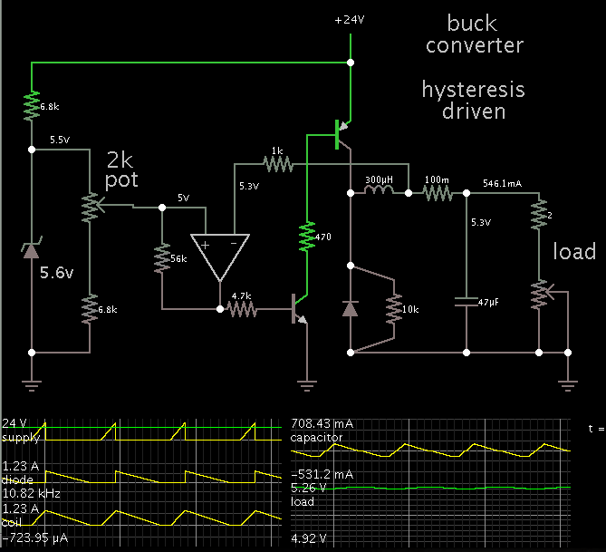
I know, regulators have feedback part. I want to know where is feedback part of this regulator?

Regards,
Princess
 

Buck, boost etc. is a circuit topology, voltage or current regulator is a circuit function. You'll find buck converters that are not used as regulators.

If a buck converter is used as a switched-mode regulator, it will implement feedback to the pulse width modulator.
 
  • Like
Reactions: Eshal

    Eshal

    Points: 2
    Helpful Answer Positive Rating
But according to our lectures, buck, boost and buck-boost is a converter and it is performing an action of regulators too. Is there any part in the circuit which can lead me to judge the circuit that it is working as a regulator too?
 

But according to our lectures, buck, boost and buck-boost is a converter and it is performing an action of regulators too. Is there any part in the circuit which can lead me to judge the circuit that it is working as a regulator too?
Hi Eshal
Please read post of FvM #2 again please . what he told ? buck converter can be used as many of the things ! one of the applications is as a regulator but you'll find many of the other applications too .
Again as FvM said , when it has a feedback you can consider it as a regulator ! ( feedback path from the out put will try to make the out put constant instead of different loads . )
I want know the difference between converters and regulators.
Each circuit or thing which can convert something into the other thing , or a voltage or a value of current into another value , have been called converter . that's all ! but a regulator ( voltage regulator or current regulator ) is a device ( circuit ) which will try to deliver the fixed voltage or current instead of different loads .
I hope you got the point .
Best Wishes
Goldsmith
 
1.

I have a book on power supplies from 1994 (by Irving Gottlieb). It has chapters which associate converters with inverters as a group. Other chapters discuss switched-coil power supplies, calling them switched regulators.

That may have been the usage then. However over the years the usage seems to have gravitated to 'switch-mode converters' or 'switch-mode power supplies' (SMPS).

To me 'regulators' means voltage regulators or current regulators.

I think of the word 'conversion' to describe the job done by switched-coil (and switched-capacitor) topologies.

2.

To see interactive animated demo's each of buck, boost, and buck-boost types (unregulated), click the following thread link.

https://www.edaboard.com/threads/268178/

They are unregulated. You act as the regulator.
 

I have understood what FvM has said.
I have a book of power electronics by M H Rashid. This book is obviously widely used book.
But it has a topic name Switched mode regulators and under this topic they have written sub topic Buck converter, Boost converter and buck-boost converter.
Are you getting my point experts? What I am saying, in regulator topic they have introduced sub topic of converters. This is confusing me a lot.
And moreover, they have introduced it as named by converters but in the operation they showed it is working as regulators too. So I want to know that which part of the Buck converter, Boost converter and buck-boost converter is actually performing a feedback action?

And I also want to know, in these switched mode regulators they have used electronic switch (transistor). Why it is good to use MOSFET as an electronic switch?

Thank you.
 

Eshal,

Sometimes words are used interchangeably, when several words can be applied to the same circuitry - even if those words describe quite different aspects of that circuit. You have to get used to it, as it happens pretty often in electronics (and elsewhere, too!)

A converter, by definition "converts" something, usually voltage, when we talk about power supplies. However, because converting a voltage without reasonably good control of the resulting voltage, nearly always we also include a regulating loop. Thus we get a voltage converter, which is also a voltage regulator. No need to get confused.

Buck, boost, and buck-boost are names of so-called topologies, as FvM already pointed out. Buck has the property of only being able to convert a higher input voltage to a lower one, boost only can convert to a higher output than the input voltage, and buck-boost is able to either produce a lower or a higher than output voltage (even if in a typical buck-boost arrangement the output voltage polarity is opposite to the input polarity).

To the basic converter one nearly always adds a circuitry to monitor the output voltage. And the converter control circuitry then regulates the converter's switch on/off -times, making an effort trying to keep the output voltage equal to some target value. That makes it to a regulator, too.

To answer your question about MOSFET as a switch: Bipolar transistors have a switching-off delay caused (mainly) by minority carriers, which have to be "emptied out" before the transistor stops conducting. That causes switching losses. For MOSFET there are no minority carriers, and therefore usually the switching losses can be made smaller. To go very detailed in the transistor theory and practice is a bit too much in a brief discussion forum text, so you have to study the textbooks for deeper descriptions. Just know that MOSFETs have lower dynamics switching losses, which is especially important on higher switching frequencies. (Of course there are also many other differences between bipolar and MOSFET transistors, and in some situations bipolar transistors are still a very good alternative.)
 
Last edited:
And moreover, they have introduced it as named by converters but in the operation they showed it is working as regulators too. So I want to know that which part of the Buck converter, Boost converter and buck-boost converter is actually performing a feedback action?

The method of regulating these converters has changed over the years. Nowadays there are controller IC's, which are designed to do all jobs: regulate, sense feedback levels, supply pulses at the right frequency and duty cycle, etc.

However in earlier days they had to use simpler components to do the job. The portion that carried power was less distinct from the portion that regulated. The functions were more dependent on each other.

And I also want to know, in these switched mode regulators they have used electronic switch (transistor). Why it is good to use MOSFET as an electronic switch?

Thank you.

This is what I gather from Gottlieb's book. It took a transition, over several years, as mosfets have become more common in switched-coil converters. It took time due to:

* Designers uncertain in earlier years as to some mosfets manufactured with an internal zener diode from gate to source, some not. (And whether protective components need to be added.)

* Designers uncertain about some mosfets having a body diode, and at what volt threshold, and how does it interact with the circuitry.

* Mosfets have an insulated gate, which can be ruined by static charge and/or high voltage spikes which are typical when sending high current through a coil and then switching it off. These risks require the addition of safeguards.

* Chip manufacturers needed time to develop techniques to deposit a P-mosfet so its characteristics would match a corresponding N-mosfet. (This had been accomplished on-chip with NPN/PNP transistors years ago.)

On the plus side is the fact that power mosfets are not prone to thermal runaway as transistors are.

I'm not an authority so I may be wrong.
 

Thank you experts!
I have understood why we are using MOSFET instead BJT. I have seen IGBT too as an electronic switch.
Here is buck converter
Capture.PNG
Here is boost converter
boost.PNG
Here is buck-boost converter
buck-boost.PNG

Can you point out which part in above each circuit is performing feedback action?

Thank you.
 

I have a book of power electronics by M H Rashid. This book is obviously widely used book.

Hi Eshal
i have it too , but unfortunately i need to confess that , Rashid's book has noting practical for dealing with ! it is just about theorem and most of the times things that are mentioned are not used in practice ! so it's impossible that i rely on that book in design process .
But it has a topic name Switched mode regulators and under this topic they have written sub topic Buck converter, Boost converter and buck-boost converter.
Of course that is a mistake ! because converters are different with regulators .
I want to know that which part of the Buck converter, Boost converter and buck-boost converter is actually performing a feedback action?
The problem is you didn't see any full circuit of an SMPS . thus you could understand that all of the circuits that you are referring to are incomplete and just served for educational purposes .
And I also want to know, in these switched mode regulators they have used electronic switch (transistor). Why it is good to use MOSFET as an electronic switch?
Because of some reasons , one of them is that for BJT you'll need to inject base current ! ( continuously base current ) . and all of the power BJTs dealing with low Beta . so consider you have a transistor with beta of 20 and you need 150 ampere as Ic . what would be the required base current ? you'll need 7.5 amperes continuously as base current so it is an awful condition .
Another problem is beta is not constant instead of different VEC ! so you can't anticipate something .
Another problem is higher price . another problem is delaying in responses and many of the problems . but it also has some advantages ! it is why IGBT has been designed ! to cover advantages of both BJT and mosfet .
Can you point out which part in above each circuit is performing feedback action?
Before that , look into this schematic that you've attached above :
It is not correct . look into the polarity or out put voltage . it should be negative not positive ! where it has been derived from ? change the polarity !
Ok let's back to your question :
Feedback will be taken from out put through the PWM driver . all of these parts are not shown in your circuits .

Best Wishes
Goldsmith
 
  • Like
Reactions: Eshal and FvM

    FvM

    Points: 2
    Helpful Answer Positive Rating

    Eshal

    Points: 2
    Helpful Answer Positive Rating
Can you point out which part in above each circuit is performing feedback action?
As goldsmith mentioned, it isn't shown at all. That's because the pulse width modulator has been omitted from the block diagrams. But the only way to control the output voltage is by changing the pwm duty cycle. You have to supplement the clock diagram by a voltage reference, an error amplifier and a pulse width modulator to implement feedback.
 

according to our lectures, buck, boost and buck-boost is a converter and it is performing an action of regulators too.

He may be describing a practical application. For example, the power adaptor of your laptop. Which have different functional block tied together.To name a few, voltage converter, voltage regulator, over current protection, ID etc.

But it has a topic name Switched mode regulators and under this topic they have written sub topic Buck converter, Boost converter and buck-boost converter.
Are you getting my point experts? What I am saying, in regulator topic they have introduced sub topic of converters. This is confusing me a lot.

Buck converter, Boost converter and buck-boost converter when respond to input output changes( with extra circuits) they become reglators called switching regulators
A switching regulator works by taking small chunks of energy, bit by bit, from the input voltage source, and moving them to the output. This is accomplished with the help of an electrical switch and a controller which regulates the rate at which energy is transferred to the output (hence the term “switching regulator”).

The energy losses involved in moving chunks of energy around in this way are relatively small, and the result is that a switching regulator can typically have 85% efficiency.Switch-mode regulators are used in devices like portable phones, video game platforms, robots, digital cameras, and your computer..

Of course that is a mistake ! because converters are different with regulators .

Many a times relevant topics are compiled together. For example if you search for a map you also find advertisment of travellers,hotels. It is good of a general idea of practical implementation of the subject. Of course it depends upon targeted audiences. For example description about "Synchronous rectification", here.
https://en.wikipedia.org/wiki/Buck_converter


See detailed description here. Also under the heading "Regulation".
https://en.wikipedia.org/wiki/Switched-mode_power_supply

Using a switching reglator IC.
https://mysite.du.edu/~etuttle/electron/elect63.htm
 

Attachments

  • switching regulators.pdf
    176.8 KB · Views: 121
Last edited:
@goldsmith
Very well description. And detailed explanation. I understood the issue why we use IGBT or MOSFET other than BJT.

@goldsmith and @FvM
I have extracted these pictures from the M.H.Rashid handbook of power electronics page#213, 215 and 216.
The circuit I showed here are as it is in the handbook.

@ALTERLINKS
I agree with you, you are right. They are hybrid circuit, say. They have combined logic in the heading of switched mode regulators with converter.
And the your provided link, I have gained one more knowledge which I didn't know before, it is that, PWM control is the chopper control and it the part which is responsible of performing feedback. Right?

Regards,
Princess
 

I have extracted these pictures from the M.H.Rashid handbook of power electronics page#213, 215 and 216.
The circuit I showed here are as it is in the handbook.

Fine. You'll also find feedback discussed at page 221f under Control Principles.
 

I have extracted these pictures from the M.H.Rashid handbook of power electronics page#213, 215 and 216.
The circuit I showed here are as it is in the handbook.
Hi Eshal
If you mean that circuit with wrong polarity of out put , then i need to advise that don't follow books blindly ! ( of course many of the books are very good but not rashid's book ! it has many of the technical mistakes and errors . )
If a handbook say an apple is blue , will you believe that ? i don't think so because you can think , that an apple will never be blue ! . isn't it ?

Best Wishes
Goldsmith
 

@FvM
Yes, Agree. I have seen it. But polarity is also an issue. It is the book which is recommended worldwide usually. So it should not have any mistake.
@goldsmith
I agree with you. I believe it is wrong. Can you suggest me any book which have good basics of power electronics. I am beginner for this course.
power electronics by Ned Mohan is also a choice and I have it.
Would you like to suggest me any then so that I could continue to study topics and ask problems here.

Thank you experts!
 

Polarity matters of course. But in the book's schematic it's just a typo, you'll find a few of it in every text book. I was under the impression, that the output polarity of the so-called "inverting buck-boost" would be quite obvious. ted mentioned it in post #7 even before you showed the circuit.

There may be more serious lacks of Rashid's book. I won't become aware of it from my mostly cursory reading.
 

Can you suggest me any book which have good basics of power electronics. I am beginner for this course.
power electronics by Ned Mohan is also a choice and I have it.
Would you like to suggest me any then so that I could continue to study topics and ask problems here.
Hi Eshal
I've read some sections of mohan book but after that i preferred to don't read it anymore .
There are many fascinating books for modern power electronics ( converters / inverters / regulators ... etc )
For instance Professor marty brown has wrote some fantastic books . one of them that can be your starting point is switch mode power supply cookbook . another good book is switching power supply desing by professor abraham i pressman . and ..... etc !
And also you need to read some articles and application notes which are widely and easily available in net !
Best Wishes
Goldsmith
 

@FvM.
Yes sir, I have noticed it in that post.
@goldsmith.
Bro, I tried to search book in which I get introduction of power electronics' articles or topics but I didn't get any good book. Your mentioned are not available on the internet to download I think.

@ALL EXPERTS!
I will continue this thread after some days. I am not going to close it now. But I will give attention to it at present because I have exams on the go. On 8 May I have paper of continuous and discrete signals. So I am preparing for exam. But I have some issues to learn related to these converters. Kindly be available to this thread.

All are thanked very much by Eshal :) :p

Regards,
Princess
 

This schematic is a buck converter with regulation added.

The entire thing could be called a regulator. It accepts a variety of supply voltages. It provides 5V to a range of loads.


The op amp:
(1) senses feedback,
(2) compares it with a reference V,
(3) provides on-off pulses to a switching device (transistor).

This illustrates the basic concept only.
Of course it is not as sophisticated as commercially available IC's.
 
Status
Not open for further replies.

Similar threads

Part and Inventory Search

Welcome to EDABoard.com

Sponsor

Back
Top