anj
Member level 3
- Joined
- Aug 16, 2012
- Messages
- 66
- Helped
- 7
- Reputation
- 14
- Reaction score
- 7
- Trophy points
- 1,288
- Location
- Rajkot, Gujarat, India
- Activity points
- 1,679
hello all..
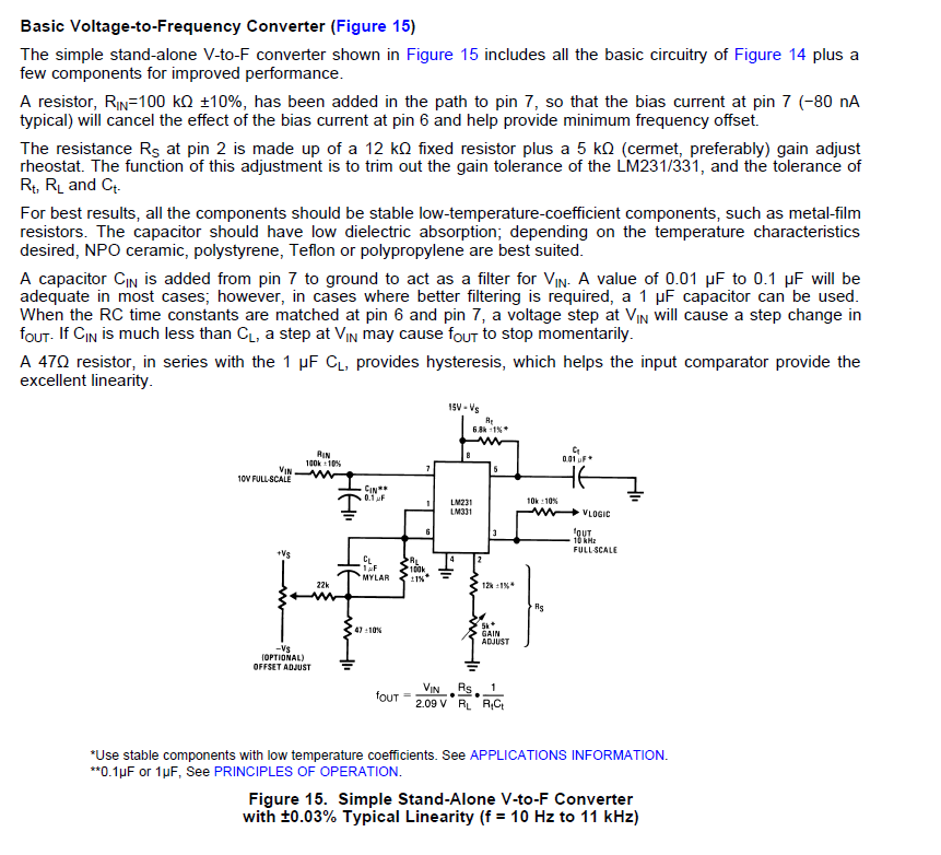
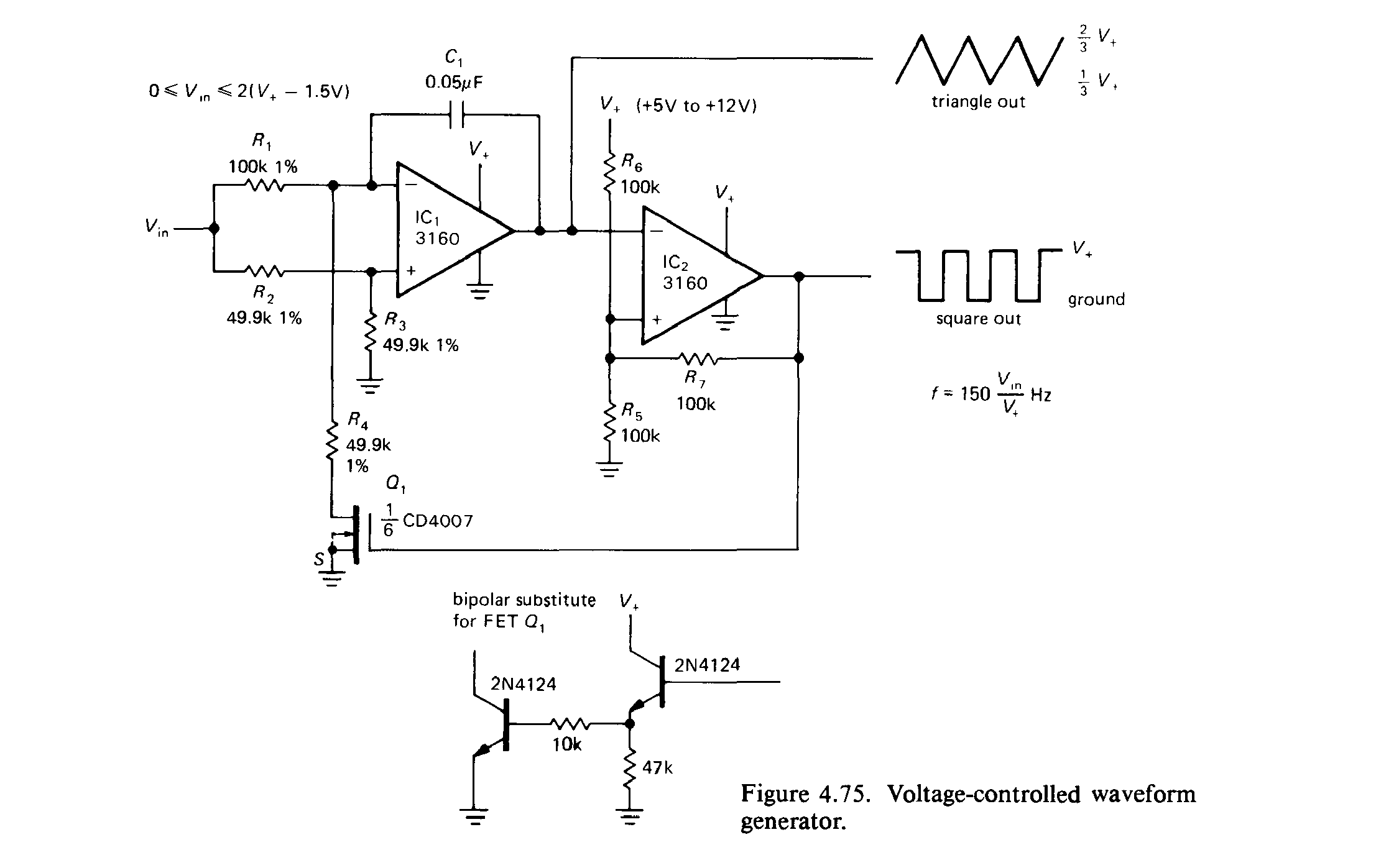
I want to convert voltage to frequency by means of any IC.
right now I am using LM331 but not getting any required output.
I can post my circuit too if anybody wants..
thanks in advance...
please suggest any reliable circuit/IC/other option..
I want to convert voltage to frequency by means of any IC.
right now I am using LM331 but not getting any required output.
I can post my circuit too if anybody wants..
thanks in advance...
please suggest any reliable circuit/IC/other option..