stevenmahoney
Junior Member level 3
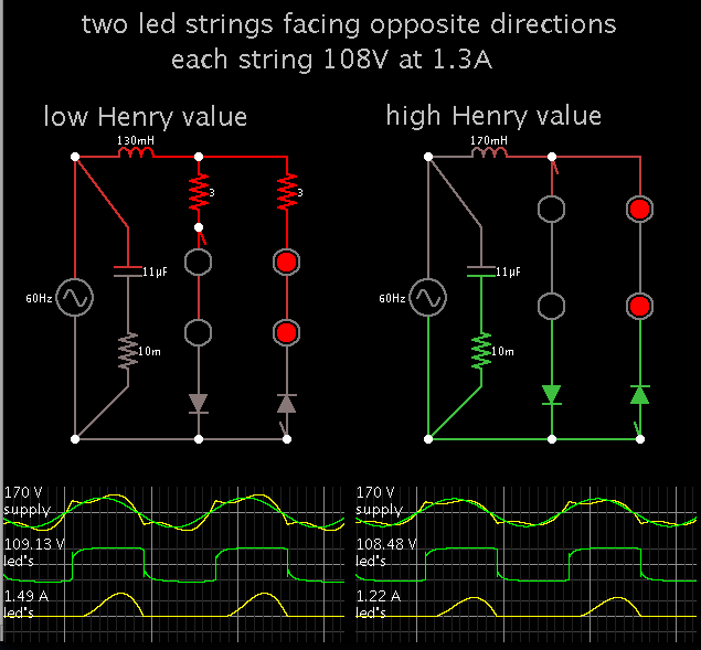
I have a simple schematics with a number of LED drivers. LED strings have a certain number of LEDs that I cannot change. In order for LEDs to operate properly, I have to feed them with 108V and 1.3A current (combined).
If I rectify 120V after diode bridge voltage increases to approximately 168V. I have excess of 32 volts (28V drops on LED drivers).
I can use a resistor or a capacitor (on AC side) to get rid off excess of 32 volts, but both are bulky (and in case of the resistor hot) solutions.
Is there any other smarter way to solve this problem? Any ideas will be appreciated.")

Steven
If I rectify 120V after diode bridge voltage increases to approximately 168V. I have excess of 32 volts (28V drops on LED drivers).
I can use a resistor or a capacitor (on AC side) to get rid off excess of 32 volts, but both are bulky (and in case of the resistor hot) solutions.
Is there any other smarter way to solve this problem? Any ideas will be appreciated.
Steven