Continue to Site

Welcome to EDAboard.com

Welcome to our site! EDAboard.com is an international Electronics Discussion Forum focused on EDA software, circuits, schematics, books, theory, papers, asic, pld, 8051, DSP, Network, RF, Analog Design, PCB, Service Manuals... and a whole lot more! To participate you need to register. Registration is free. Click here to register now.

[SOLVED] ADS : How to simulate frequency dependent resistor (and incuctance)

Status
Not open for further replies.

Meryl

Newbie level 6
Joined
Apr 19, 2013
Messages
11
Helped
1
Reputation
2
Reaction score
1
Trophy points
1,283
Activity points
1,345
ADS : How to simulate frequency dependent resistor (and inductance)

Cc everyone

Please, I want to know how to simulate a frequency dependent resistor and inductance, the problem is that I don't know how to write the equation of the resistor, and where, here is the equation of my component R, it is for an electrical modeling purpose:

R = sqrt((R_ac)^2 + (R_dc)^2);

and R_ac = a/ ((b*Skin) - (pi*(Skin^2))) ;
R_dc = 5.94e-4
the variable skin that represent the skin effect that occurs to a resistance at high frequency: Skin = 1./sqrt(pi*freq*5.9524e7)
a=1.68e-12 , b = 1.884e-4;

I can't simulate S-parameters because ADS does'nt allows frequency dependent Resistor and inductance, please give me a simple way to solve this problem.

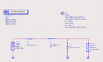
here is my electrical model : model_tgv.PNG

Best regards
Thanks :wink:
 

Attachments

  • model_tgv.PNG
    model_tgv.PNG
    19.7 KB · Views: 823
Last edited:

The error message is giving you guidance on what needs to be done:

Improper frequency dependence in resistor parameter.
Use the Y_Port, Z_Port or S_Port device instead.

ADS provides a set of equation based elements that can be controlled by functions that are dependant on the simulation frequency.

In this case instead of the ideal resistor use the Z1P_Eqn, a 2 pin device, and set the Z[1,1] parameter to have a real part that is the required frequency dependant resistance value. For a resistor the imaginary part of Z[1,1] is 0 so this does not need to be defined as the default is 0.

You schematic becomes:

schematic_fdr.png

and this simulates giving the expected frequency varying resistance.

dds_fdr.png

The Zin plot is calculated as Z[1,1] - 50 to take off the effect of the load resistance and plot the equivalent series resistance of the Z1P_Eqn.
 
I appreciate your help RealEAL, this is exactly what I need, but I want to know, why did you add "Zin" ? I tried the same schematic without it and it gives the same results

Best Regards
 
It was just an easy way to see Z[1,1]. You would not see that normally when doing a regular s-parameter simulation. Of course you could write an equation to calculate Z[1,1] from S[1,1] but this measurement item does if for you. It does not change the results for the resistor. Just an extra measurement.

I could have done something similar by simply plotting the value of the variable Rtgv but that would be only the resistor value only and not the equivalent series resistance of the entire circuit. Almost the same but not quite:

table_fdr.png
 
Last edited:
Status
Not open for further replies.

Part and Inventory Search

Welcome to EDABoard.com

Sponsor

Back
Top