Continue to Site

Welcome to EDAboard.com

Welcome to our site! EDAboard.com is an international Electronics Discussion Forum focused on EDA software, circuits, schematics, books, theory, papers, asic, pld, 8051, DSP, Network, RF, Analog Design, PCB, Service Manuals... and a whole lot more! To participate you need to register. Registration is free. Click here to register now.

bjt amplifier design

Status
Not open for further replies.

sam_s.pitt

Newbie level 4
Joined
Sep 24, 2012
Messages
6
Helped
0
Reputation
0
Reaction score
0
Trophy points
1,281
Activity points
1,329
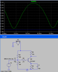
I want to design a single stage common emitter amplifier. I have read a manual about this. It recommends to choose Vcc=3Vce in a self bias configuration. (Vcc=bias source). I know that in order to have the maximum swing in output, the Q-point must be in the middle of the ac load line, which means that Vce=Vcc/2. can anyone describe this contradiction to me?
Moreover, I would be thankful if anyone introduce me a good book or manual on designing bjt amplifiers.
 

If you want maximum swing, then you desire output ranging between 0V and supply V. This is done by operating the transistor between its minimum 'On' resistance, and being nearly Off. Hence the output is centered around Vcc/2.

However response becomes non-linear when operated close to its minimum 'On' resistance. So if you input a sinewave, it gets turned into an ocean wave at the collector output:

3620047000_1366175880.gif


(I had to draw it manually because I could not duplicate the effect in simulation.)

The waveform is distorted. This is not necessarily predicted by load lines, etc.

To preserve a sinewave shape, the waveform must be lifted upward, away from the transistor's non-linear region.
This means you cannot operate the transistor with maximum swing. You need to reduce amplitude.

As a result the output centerline is no longer Vcc/2. More like 2/3 of Vcc.
I believe this is the reason for the recommendation. It's intended to operate the transistor in its linear region.
 

I know that in order to have the maximum swing in output, the Q-point must be in the middle of the ac load line, which means that Vce=Vcc/2.
That's only true if there is no external load on the amplifier.

Typically, there is some load resistance capacitively coupled to the output. In that case, the collector pull-up resistor can not pull the output all the way up to Vcc, but the transistor can still pull the output all the way down to ground, so setting the Q-point at Vce = Vcc/2 does not give max output.

When the load resistance is equal to the collector pull-up resistor, then max output is obtained when the Q-point is set at Vce = Vcc/3.

the transistor's non-linear region.
I agree transistors are non-linear. In fact they don't have a linear region, the relationship between Vbe and collector current is exponential. This causes distortion proportional to the signal amplitude.

The usual way to reduce the distortion is with negative feedback. With common emitter amplifiers, that's most easily done by adding a resistor in series with the emitter. That also reduces gain and increases the input impedance.

e.g. An emitter resistor with a quiescent DC voltage of 240mV across it will:
  • Reduce gain by a factor of 10
  • Increase input impedance by a factor of 10
  • Reduce distortion by a factor of 10 for the same output amplitude
  • Reduce distortion by a factor of 100 for the same input amplitude

BTW, it's fairly easy to estimate the distortion in a common emitter amplifier. With no emitter resistor, the percentage distortion at the output is roughly equal to the amplitude of the input signal in mV. e.g. 5mV input gives 5% distortion at the output.
 
If you want maximum swing, then you desire output ranging between 0V and supply V. This is done by operating the transistor between its minimum 'On' resistance, and being nearly Off. Hence the output is centered around Vcc/2.

However response becomes non-linear when operated close to its minimum 'On' resistance. So if you input a sinewave, it gets turned into an ocean wave at the collector output:

3620047000_1366175880.gif


(I had to draw it manually because I could not duplicate the effect in simulation.)

The waveform is distorted. This is not necessarily predicted by load lines, etc.

To preserve a sinewave shape, the waveform must be lifted upward, away from the transistor's non-linear region.
This means you cannot operate the transistor with maximum swing. You need to reduce amplitude.

As a result the output centerline is no longer Vcc/2. More like 2/3 of Vcc.
I believe this is the reason for the recommendation. It's intended to operate the transistor in its linear region.
The response at the collector is enhanced when the transistor is near full conduction and it is compressed when the transistor is near cutoff.

So it is best to bias the base so that the collector is a little less than Vcc/2 and not what you said.
 

Attachments

  • transistor distortion.PNG
    transistor distortion.PNG
    21 KB · Views: 73
The response at the collector is enhanced when the transistor is near full conduction and it is compressed when the transistor is near cutoff.

So it is best to bias the base so that the collector is a little less than Vcc/2 and not what you said.

Yes. Your simulation shows a scope trace of the same thing I observed. (My drawing is an inverted version.)

I guess I did my experiments with a PNP transistor, because I recall thinking 'that output looks just like ocean waves'.
 

Thanks for the helpful responses.
Anyone could propose a good book or manual for designing different types of bjt and fet amplifiers?
 

"The art of electronics" by Horowitz & Hill
 

    V

    Points: 2
    Helpful Answer Positive Rating
Status
Not open for further replies.

Similar threads

Part and Inventory Search

Welcome to EDABoard.com

Sponsor

Back
Top