Continue to Site

Welcome to EDAboard.com

Welcome to our site! EDAboard.com is an international Electronics Discussion Forum focused on EDA software, circuits, schematics, books, theory, papers, asic, pld, 8051, DSP, Network, RF, Analog Design, PCB, Service Manuals... and a whole lot more! To participate you need to register. Registration is free. Click here to register now.

[SOLVED] Replacing special capacitor

Status
Not open for further replies.

mozart1973

Junior Member level 2
Joined
Apr 16, 2013
Messages
21
Helped
0
Reputation
0
Reaction score
0
Trophy points
1,281
Activity points
1,416
Hi!

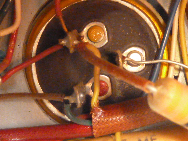
In my old radio sits a large capacitor next to the rectifier. The radio hums. I have a suspicion that this is must likely causing it. The problem is that it looks special. Not with one value like the others but two values. It has three pins and one is marked red and one marked yellow. On it is written

48uf red outer section
48uf yellow

320/350 v DC

Type EAL

2207 eqi

Is this what is called a dual capacitor and can I replace it with two single 48uf capacitors in parallel?

regards
ath
 

You can replace it by two regular capcitors. In most cases, both capacitors are not parallel connected, but may be they are in your radio. If they are paralleled, a single 100 µF capacitor can be used as replacement.
 
  • Like
Reactions: tpetar

    tpetar

    Points: 2
    Helpful Answer Positive Rating
Yes you can replace it with two capacitors, one for red and one for yellow.
 

Btw, what is the benefit of using multiple capacitors. Is it just to save space?

- - - Updated - - -

You can replace it by two regular capcitors. In most cases, both capacitors are not parallel connected, but may be they are in your radio. If they are paralleled, a single 100 µF capacitor can be used as replacement.

How do I know if they are parallel or seriel?
 

If the red pin is connected to the yellow pin, then they are connected in parallel. I doubt they are connected in series.
 

OK, you need two capacitors then. One for red to silver, and one for yellow to silver. If you use electrolytic caps, be careful to get the polarity right. I would guess red and yellow are positive and silver is negative, but it's best to check.
 

By design of electrolytic capacitors (negative terminal connected to aluminium jacket) dual capacitors have always common negative terminal and are connected in parallel.
 

By design of electrolytic capacitors (negative terminal connected to aluminium jacket) dual capacitors have always common negative terminal
That's what I thought, but wasn't sure. They're not really in parallel though, as the positive terminals are separate.

From the given voltage rating and capacitance, I'd guess it's a valve radio with CRC or CLC filtering of the B+ supply.
 

Yes, of course the dual capacitor design makes no sense if you only want paralleled capacitors. These devices have been widely used with tube radios, mostly for CRC filtering as you mentioned.
 

Yes, it's an old tube radio.
I managed to find the company that made the capacitor. Still exists live and well. But they don't have a dual capacitor of the same values any more.
 

Status
Not open for further replies.

Part and Inventory Search

Welcome to EDABoard.com

Sponsor

Back
Top