Continue to Site

Welcome to EDAboard.com

Welcome to our site! EDAboard.com is an international Electronics Discussion Forum focused on EDA software, circuits, schematics, books, theory, papers, asic, pld, 8051, DSP, Network, RF, Analog Design, PCB, Service Manuals... and a whole lot more! To participate you need to register. Registration is free. Click here to register now.

diffrential amplifer output signal not stable.

Status
Not open for further replies.

seyyah

Advanced Member level 2
Joined
Oct 7, 2001
Messages
646
Helped
8
Reputation
16
Reaction score
8
Trophy points
1,298
Activity points
6,233
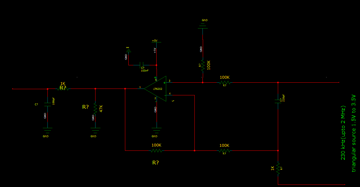
I am trying to buffer a signal on a capacitor using lt6202 using differential configuration. All resistors are fixed 100kohm in the differential configuration. The signal at the input is a clear signal oscillating between 1.5 to 3.5V @ 230kHz. The signal can be seen at the output but it is not stable. It is driving a 47k load with parallel to 1k and 220nF first order filter. It is fed from a single supply of 5V. There are a lot of ghost images of the original signal. I think the phase is continously shifting but the amplitude and shape of the signal seems to be ok mostly (some distortion there also). What may cause this, how should i choose opamp and resistors for this kind of application and what should i care of? Thanks.
 

A 100 MHz OP like LT6202 will be most likely unstable with 100K feedback resistor by input capacitance effect unless using small parallel capacitors. Pure resistive feedback networks should have 1k up to maximum 5k resistance. Noise and offset voltages will be bad with 100k feedback resistors as well.
 

A 100 MHz OP like LT6202 will be most likely unstable with 100K feedback resistor by input capacitance effect unless using small parallel capacitors. Pure resistive feedback networks should have 1k up to maximum 5k resistance. Noise and offset voltages will be bad with 100k feedback resistors as well.

I was suspecting of that but i need to introduce high impedance to the source. May be the instrumentation amplifier is the solution here but in this configuration can you suggest something like a suitable part or something another? How should we use capacitors you mentioned about? Thanks
 

The capacitors would go parallel to the feedback resistor(s), 0.5 or 1 pF should be sufficient. I keep my comment that 100k resistors don't fit LT6202 well.
I also support the question in post #2.


The schematic is attached
 

Status
Not open for further replies.

Similar threads

Part and Inventory Search

Welcome to EDABoard.com

Sponsor

Back
Top