Continue to Site

Welcome to EDAboard.com

Welcome to our site! EDAboard.com is an international Electronics Discussion Forum focused on EDA software, circuits, schematics, books, theory, papers, asic, pld, 8051, DSP, Network, RF, Analog Design, PCB, Service Manuals... and a whole lot more! To participate you need to register. Registration is free. Click here to register now.

current through series/parallel circuit

Status
Not open for further replies.

sachinsk

Newbie level 4
Joined
Feb 18, 2013
Messages
5
Helped
0
Reputation
0
Reaction score
0
Trophy points
1,281
Activity points
1,320
Hi,

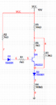
I want to calculate current through the circuit present in attached image.

V5,V6 are the voltage drops of diodes, used directly voltage drops just for easy calculation/representation.

I need formula or the way to calculate current through this circuit.
The parallel combination troubling me a lot.
Capture.PNG
 

I think Millman's theorem wont help me.
Below is my simplified circuit in which am suppose to calculate total current when the transistor is ON.
Consider diode drop as 1V, transistor Vce as 0.7.

when transistor is ON, we see 3 current loops i.e. R2,D1,R1,U1,D2,R4 and R5,R6,U1,D2,R4 and R5,R3,D2,R4.
so how to calculate total current I1,+I2+I3 ?
 

Attachments

  • transistor circuit.PNG
    transistor circuit.PNG
    12.8 KB · Views: 142

The circuit in post 1 is quite easy. You can simplify it like in the pic below.

The circuit in post 3 is much more difficult. There are 2 possibilities:
  • If the transistor is saturated, then we can estimate Vce = 0.1V.
  • If the transistor is not saturated, then Ic = Ib * hFE.
In either case you need to write out a set of linear equations describing the relationship between the various voltages and currents in the circuit, then solve the equations. I'll have a go at that later.


Calculate current through each path. Once you find Ic and Ib then voltage across R3 is equal to Vr3 = Vce + IcR6 and current through R3 is Vr3/R3.
 

Below is my simplified circuit in which am suppose to calculate total current when the transistor is ON...
Here's the original circuit:


Let's start by assuming that the transistor is saturated. As an approximation, let's say Vce = 0.1V, Vbe = 0.7V, and the diode voltage drops are also 0.7V.

We can replace the diodes and transistor with voltage sources like this:


Then we can simplify by combining the series resistors and voltage sources on the left to get this equivalent circuit:


Looking at that circuit, we can describe the currents in terms of the voltages like this:

  1. I1 = (10 - 1.4 - Vnode2) / 8K
  2. I2 = (Vnode1 - 0.1 - Vnode2) / 1K
  3. I3 = (Vnode1 - Vnode2) / 1.5K
  4. I2 + I3 = (10 - Vnode1) / 10K
  5. I1 + I2 + I3 = (Vnode2 - 0.7) / 100K

That gives you 5 equations with 5 unknowns, which should be fairly easy to solve. After calculating the values of I1, I2, I3, Vnode1 and Vnode2, you need to check that the values are reasonable, and support the initial assumption that the transistor is saturated. e.g. I1 and I2 should both be positive, and I2/I1 should be less than the normal value of hFE.

If that doesn't work out, then you have to start over, assuming the transistor is not saturated. In that case, we don't know the value of Vce, so equn 2 above changes to "I2 = (Vnode1 - Vce - Vnode2) / 1K", giving us an extra unknown variable. But this time we know that I2 = hFE * I1, so now we have 6 equations with 6 unknowns:

  1. I1 = (10 - 1.4 - Vnode2) / 8K
  2. I2 = (Vnode1 - Vce - Vnode2) / 1K
  3. I3 = (Vnode1 - Vnode2) / 1.5K
  4. I2 + I3 = (10 - Vnode1) / 10K
  5. I1 + I2 + I3 = (Vnode2 - 0.7) / 100K
  6. I2 = I1 * hFE
 

The circuit in post 1 is quite easy. You can simplify it like in the pic below.

The circuit in post 3 is much more difficult. There are 2 possibilities:
  • If the transistor is saturated, then we can estimate Vce = 0.1V.
  • If the transistor is not saturated, then Ic = Ib * hFE.
In either case you need to write out a set of linear equations describing the relationship between the various voltages and currents in the circuit, then solve the equations. I'll have a go at that later.


this looks interesting..
If V5,V6 are not equal, what we need to do?
I mean is there any formula if 2 resistors,Diodes/voltage sources are in parallel like in this case..

- - - Updated - - -

Here's the original circuit:


Let's start by assuming that the transistor is saturated. As an approximation, let's say Vce = 0.1V, Vbe = 0.7V, and the diode voltage drops are also 0.7V.
..

That gives you 5 equations with 5 unknowns, which should be fairly easy to solve. After calculating the values of I1, I2, I3, Vnode1 and Vnode2, you need to check that the values are reasonable, and support the initial assumption that the transistor is saturated. e.g. I1 and I2 should both be positive, and I2/I1 should be less than the normal value of hFE.

If that doesn't work out, then you have to start over, assuming the transistor is not saturated. In that case, we don't know the value of Vce, so equn 2 above changes to "I2 = (Vnode1 - Vce - Vnode2) / 1K", giving us an extra unknown variable. But this time we know that I2 = hFE * I1, so now we have 6 equations with 6 unknowns:


[/LIST]

I think am wrong in this case.Now in great confusion whether the transistor is ON or OFF?
How to conclude that the transistor is ON/OFF?
As per simulation,transistor is OFF. But whats reason?

Which current is causing it to turn OFF.. Ic or Ib which are in uA..
Is this uA main reason for OFF state?
 

t
I think am wrong in this case.Now in great confusion whether the transistor is ON or OFF?
How to conclude that the transistor is ON/OFF?
As per simulation,transistor is OFF. But whats reason?
My simulation shows the transistor is on, and is saturated.


BTW: Did you try solving the equations?
If so, did you get the right answers?
 

Status
Not open for further replies.

Similar threads

Part and Inventory Search

Welcome to EDABoard.com

Sponsor

Back
Top