The_Dutchman
Member level 1
Hello,
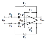
I'm designing a differential sample-and-hold. I have some specifications I have to met. The maximum supply voltage is 1.2V and there is chosen to be 100mV margins on the supply lines leaving a voltage swing of 1V from 0.1V to 1.1V. The kind of circuit I am designing is the differential equivalent of this circuit:

Like this:

The switches generate thermal noise which is integrated on the sampling capacitor and thus lead to a noise power. This gives rise to a finite SNR.
For the given minimum SNR of 82dB I need to calculate the minimal size of the sampling capacitor for a single-ended and differential circuit with a maximum swing sine wave.
For the single-ended case I've found:
\[
\begin{eqnarray}
V_{S_{pp}} &=& 1V -> V_{S_{RMS}}=\frac{0.5V}{\sqrt{2}} -> V_{S_{RMS}}^2 = 0.125 V^2 \nonumber\\
V_{noise}^2 &=& \frac{k T}{C_H} \nonumber\\
SNR &=& 10 \cdot \log _{10}\left(\frac{V_{S_{RMS}}^2}{V_{noise}^2}\right) = 82 dB \nonumber\\
C_H &=& \frac{k T \cdot 10^{\frac{SNR}{10}}}{V_{S_{RMS}}^2} = \frac{1.38056\cdot 10^{-23} \cdot 300 K \cdot 10^{8.2}}{0.125V^2}=5.25pF \nonumber
\end{eqnarray}
\]
For the differential case I'm kind of confused. I see that the resistance doesn't come in to play because as R increases noise increases, but also the bandwith becomes smaller. However I think that the noise power must be bigger, as we have 2 noise sources now. Also the signal power increases because there is a differential signal of 2Vpp. This is what I've come up with, but I don't know if it is correct. I can't seem to find where I have to put the extra noise power?
\[
\begin{eqnarray}
V_{S_{pp}} &=& 2V -> V_{S_{RMS}}=\frac{1V}{\sqrt{2}} -> V_{S_{RMS}}^2 = 0.5 V^2 \nonumber\\
V_{noise}^2 &=& 2 \cdot \frac{k T}{C_H} \nonumber\\
SNR &=& 10 \cdot \log _{10}\left(\frac{V_{S_{RMS}}^2}{V_{noise}^2}\right) = 82 dB \nonumber\\
C_H &=& 2 \cdot \frac{k T \cdot 10^{\frac{SNR}{10}}}{V_{S_{RMS}}^2} = 2\cdot \frac{1.38056\cdot 10^{-23} \cdot 300 K \cdot 10^{8.2}}{0.5V^2}=2.62pF \nonumber
\end{eqnarray}
\]
EDIT: as the peak signal value in differential circuit is double of that of single ended means that the power of the signal goes times 4. The noise only doubles because there are 2 noise sources now, so I guess the SNR of differential circuits is always 3dB higher than of the same single-ended circuits. But is the capacitor used in the calculations than a differential capacitor or 2 single ended capacitors? I think each of the capacitors in the differential circuit becomes half the capacitor of the single ended circuit.
Thanks in advance,
I'm designing a differential sample-and-hold. I have some specifications I have to met. The maximum supply voltage is 1.2V and there is chosen to be 100mV margins on the supply lines leaving a voltage swing of 1V from 0.1V to 1.1V. The kind of circuit I am designing is the differential equivalent of this circuit:

Like this:

The switches generate thermal noise which is integrated on the sampling capacitor and thus lead to a noise power. This gives rise to a finite SNR.
For the given minimum SNR of 82dB I need to calculate the minimal size of the sampling capacitor for a single-ended and differential circuit with a maximum swing sine wave.
For the single-ended case I've found:
\[
\begin{eqnarray}
V_{S_{pp}} &=& 1V -> V_{S_{RMS}}=\frac{0.5V}{\sqrt{2}} -> V_{S_{RMS}}^2 = 0.125 V^2 \nonumber\\
V_{noise}^2 &=& \frac{k T}{C_H} \nonumber\\
SNR &=& 10 \cdot \log _{10}\left(\frac{V_{S_{RMS}}^2}{V_{noise}^2}\right) = 82 dB \nonumber\\
C_H &=& \frac{k T \cdot 10^{\frac{SNR}{10}}}{V_{S_{RMS}}^2} = \frac{1.38056\cdot 10^{-23} \cdot 300 K \cdot 10^{8.2}}{0.125V^2}=5.25pF \nonumber
\end{eqnarray}
\]
For the differential case I'm kind of confused. I see that the resistance doesn't come in to play because as R increases noise increases, but also the bandwith becomes smaller. However I think that the noise power must be bigger, as we have 2 noise sources now. Also the signal power increases because there is a differential signal of 2Vpp. This is what I've come up with, but I don't know if it is correct. I can't seem to find where I have to put the extra noise power?
\[
\begin{eqnarray}
V_{S_{pp}} &=& 2V -> V_{S_{RMS}}=\frac{1V}{\sqrt{2}} -> V_{S_{RMS}}^2 = 0.5 V^2 \nonumber\\
V_{noise}^2 &=& 2 \cdot \frac{k T}{C_H} \nonumber\\
SNR &=& 10 \cdot \log _{10}\left(\frac{V_{S_{RMS}}^2}{V_{noise}^2}\right) = 82 dB \nonumber\\
C_H &=& 2 \cdot \frac{k T \cdot 10^{\frac{SNR}{10}}}{V_{S_{RMS}}^2} = 2\cdot \frac{1.38056\cdot 10^{-23} \cdot 300 K \cdot 10^{8.2}}{0.5V^2}=2.62pF \nonumber
\end{eqnarray}
\]
EDIT: as the peak signal value in differential circuit is double of that of single ended means that the power of the signal goes times 4. The noise only doubles because there are 2 noise sources now, so I guess the SNR of differential circuits is always 3dB higher than of the same single-ended circuits. But is the capacitor used in the calculations than a differential capacitor or 2 single ended capacitors? I think each of the capacitors in the differential circuit becomes half the capacitor of the single ended circuit.
Thanks in advance,
Last edited: