Continue to Site

Welcome to EDAboard.com

Welcome to our site! EDAboard.com is an international Electronics Discussion Forum focused on EDA software, circuits, schematics, books, theory, papers, asic, pld, 8051, DSP, Network, RF, Analog Design, PCB, Service Manuals... and a whole lot more! To participate you need to register. Registration is free. Click here to register now.

SG3525A based Pushpull Converter Stability issue

Status
Not open for further replies.

manohar.sathish

Newbie level 4
Joined
Aug 30, 2012
Messages
6
Helped
0
Reputation
0
Reaction score
0
Trophy points
1,281
Activity points
1,348
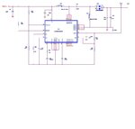
HI, I am using SG3525A for controlling Push-Pull Converter.
Our entire circuit comprises of Dc-Dc section , followed by a DC-AC section. Its a 800VA Home Inverter.

DC-Dc Specifications:
Push pull configuration
Input Voltage : 10-17V DC
Input current : 80A @ 10V Input
Output : 350V DC nominal
Watts : 800VA


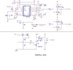
DC-AC Specification:
Full Bridge configuration,20KHz
Output Voltage : 230V AC nominal
Output current: 4.44A Max


The inverter section alone tested at full load (upto 600W) and its working fine.
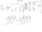
DC-Dc Section tested at no load (with input range 10V-17V) @ 100Khz, 56Khz,16Khz


But I am facing issues in the integration of DC-DC and DC-AC section.

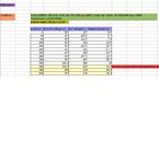
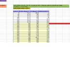
1) @ 56KHz For Input voltage upto 10V-15V the AC output is fine. But if Ie increase the voltage above 15V , the DC Link Voltage & AC output Flickers.( for 40W & 60W load tested)

SG3525A : Rt =4.7KOhm, Ct=2.7NF, Css pg1.JPGpg2.JPGpg3.JPG=1uF

2) @100KHz For input voltage upto 10V-15V the AC output is fine. But if Ie increase the voltage above 15V , the DC Link Voltage & AC output Flickers..( for 40W & 60W load tested)

SG3525A : Rt =4.7KOhm, Ct=1.5nF, Css=1uF


For both cases, Transformer used is :

Core : ETD 54 Ferrite
Turns ratio: 2:65
Frequency range : upto 500KHz.

Kindly suggest a solution for this flickering and instability issue.
 

But if Ie increase the voltage above 15V , the DC Link Voltage & AC output Flickers
Flickers isn't a very clear specification, it might be a trivial controller instability. Did you try to reduce the voltage control loop gain?
 
Try increasing C11 from .68uF to 2.2uF.
 

The error amp of SG3525A's Inverted input is connected to 5.1V reference which is generated internally by the IC itself. The non inverted input is connected to the Voltage feedback. Voltage Feedback loop is through an isolated linear optocoupler. Feedback circuit gives 1:1 output. i.e as per the circuit @350V DC the input of Linear optocoupler is 5.1 then its isolated output also gives 5.1V. Based on the comparision of these two inputs of opamp, the IC adjust the PWM.

The Flickering happens due to DC link instability. At this time I captured both pulses of Pushpull. Its behaviour is as follows.

1. Instantly both pulses are ON (i.e at 180 degree interval, no clash between pulses) then completely OFF for a long time.
2. At this ON period DC link voltage boosted to around 360V and suddenly drops to very low level (since we connected bulb load at the output of Inverter )
3. And the process continues, which causing Instant ON and OFF of the bulb load i.e the Flicker I meant to say.
The pulses are not regular.

If the input voltage is less than 15V , the circuit works fine.
Even , I tested DC-DC section alone at no load. At this , I am getting constant 350 Volt DC for 10V-17V input range.
 

From your circuit micro processor is controlling the shut down pin may be the over voltage protection circuit function is activating
 

Ya . Let me try this. Can you say how to calculate the C11, C37. They provides loop compensation for the error amplifier I think.
 

Hi all, The flickering problem above mentioned got cleared now. Found the 12V supply for SG3525A got dipping to 7V and so the things happened. Now I am feeding with external 12V supply and it is stable for load upto 640W load. But the DC link is the problem now. Upto 240W the DC link is stable at 366V . Beyond that the DC link starts reducing gradually as the load increases. I tried with different transformer turns.

Please find the test report attached.
And i altered the feedback circuit as attached.


And another one problem I am facing is only one leg of the DC-DC pushpull section gets heated more than the other.
so my questions are
1) why DC link is not stable.
2) Why only one leg is heating
3) What could be the reason for dropping of 12V supply?

Kindly suggest.

- - - Updated - - -

Hi, Please find the attached test report for different transformer turns.
 

Attachments

  • 12V supply.JPG
    12V supply.JPG
    41.5 KB · Views: 157
  • Driver and Feedback.JPG
    Driver and Feedback.JPG
    57.9 KB · Views: 229
  • Push pull section.JPG
    Push pull section.JPG
    72.2 KB · Views: 196
  • test report 1.JPG
    test report 1.JPG
    81 KB · Views: 133
  • test report 2.JPG
    test report 2.JPG
    61.2 KB · Views: 114
  • test report 3.JPG
    test report 3.JPG
    76.6 KB · Views: 115

Try interchange G1, G2 inputs of power module and see if same side gets warm again.
 

well in my own design c11 is replaced with 100k resistor and the shut down pin get 2.5v,also i can see that your output voltage is not stable with increase in load,try to pull down your pin 10 of the shut down pin and control your output voltage to e stable and heating of one side might be from your winding of the transformer.
 

One leg heating could be due to staircase saturation. Do you have any way measuring the primary current of each leg?

For the voltage sagging at high load, you should look and see if your duty cycle is hitting its limits. If so, you may need to redesign the transformer. If the duty cycle isn't maxing out, then your feedback loop doesn't have enough gain.


I measured the current flowing through each leg upto 240W. They are showing same value for both.
After this 240W load, the pulse output from SG3525A reaching its MAX 0.44 duty and stays constant.
 

You need to redesign trafo. Voltage lost are too much. Are you use litz wire? First need to increase wire section surface (minim 3 times) and also need to increase trafo ratio by about 20%.
 

Hi All,

Now, I got the DC Link stability problem solved :)

I think it is due to staircase saturation.
I felt the DC-DC switching frequency is too high as it may create heavy losses. So I changed that to 20KHz.
Now both DC-DC and DC-AC section switches at 20KHz.
Then, I Increased the Transformer primary ratio into 3. i.e 3:140 turns.

I tested upto 640W load and the DC link is stable at 368V :)

Thanks for all your support :)

I measured the leg current of both legs at each step. one leg current is always higher than the other. And at full load 640W , the current difference between the two leg is 4A. Is this in allowable range???
 

Hi All,

I measured the leg current of both legs at each step. one leg current is always higher than the other. And at full load 640W , the current difference between the two leg is 4A. Is this in allowable range???

How do you pack your windings? Can you give an illustration of the packing?
 

Hi All,

Now, I got the DC Link stability problem solved :)

I think it is due to staircase saturation.
I felt the DC-DC switching frequency is too high as it may create heavy losses. So I changed that to 20KHz.
Now both DC-DC and DC-AC section switches at 20KHz.
Then, I Increased the Transformer primary ratio into 3. i.e 3:140 turns.

I tested upto 640W load and the DC link is stable at 368V :)

Thanks for all your support :)

I measured the leg current of both legs at each step. one leg current is always higher than the other. And at full load 640W , the current difference between the two leg is 4A. Is this in allowable range???
Changing the turns ratio from 2:65 to 3:140 means that your average primary referred voltage must have gone from 10.77V to 7.5V (or 5.385V per turn to 2.5V per turn). On top of that, changing the frequency from 56KHz to 20KHz means the primary volt time product must have changed from 192.3 V*us to 375 V*us (or 96.15 V*us per turn to 125 V*us per turn). So if anything, you must have actually increased the magnetizing flux a bit. If saturation was the problem, then you almost certainly didn't fix it.

The best way to observe staircase saturation is to look at the currents in the secondary diodes, that way you can see magnetizing current by itself (during the dead time). If it's unbalanced significantly then you've got a problem. Also look for saturation by changes in the current slope vs bias current.
 
Status
Not open for further replies.

Similar threads

Part and Inventory Search

Welcome to EDABoard.com

Sponsor

Back
Top