Continue to Site

Welcome to EDAboard.com

Welcome to our site! EDAboard.com is an international Electronics Discussion Forum focused on EDA software, circuits, schematics, books, theory, papers, asic, pld, 8051, DSP, Network, RF, Analog Design, PCB, Service Manuals... and a whole lot more! To participate you need to register. Registration is free. Click here to register now.

220V/250W inverter HELP ME OUT !!!!!!

Status
Not open for further replies.

"electri"

Newbie level 4
Joined
Mar 18, 2013
Messages
6
Helped
0
Reputation
0
Reaction score
0
Trophy points
1,281
Activity points
1,319
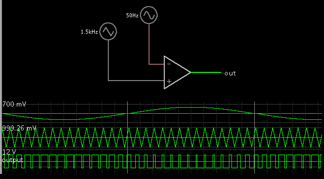
How to implement controller in sine wave inverter? according to my knowledge if output (sine wave ) is compared with the a reference signal (sine wave) the output is a pulse wave. but i need a sine output for comparison with the triangular wave to generate PWM for the gate base drive. Kindly help me in this project .
 

Not sure if this is the answer you're looking for, but here is the concept for obtaining PWM from a sine and triangular wave:


i found out that there is no need of controller in inverter, inverter can be made according to the specification without using controller.... thanks for your help :)
 

The output of your circuit is high frequency PWM modulated with a low frequency sinewave.
Use it to drive some Mosfets that feed a transformer, filter the high voltage then the output is a sinewave inverter without any voltage regulation.
 

Actually i want to minimize the the sound produced by the fans (white noise) which would run by inverter , i have searched out that these sounds are produced due to the presence of unfiltered harmonics (other than fundamental harmonic).how would i achieve the the proper sinewave ?
 

The frequency of your PWM is much too low (only 1.5kHz) so the filter does not do much. If the LC filter is -3dB at 250Hz then there is plenty of output at 1.5kHz, 3kHz, 4.5kHz and many higher harmonics.

If the PWM frequency is 30kHz or more then the filter can remove the 1.5khz fundamental plus all the harmonics but you might need a special high frequency ferrite-core transformer.
 

The frequency of PWM is 1.2khz in my project .What type of lowpass filter would i required for better filtering ? does brickwall serves the purpose or should i use butterworth filter?
which type of filter will give desired pure sinewave (as much as possible) output of 220V .
 

Your fundamental frequency is much too low. It should be above 20kHz so it is not audible.
The difference between your 50Hz output and your 1.2kHz fundamental is only 5 octaves. For an LC output filter to not attenuate your 50Hz then its cutoff should be at least 250Hz. Then the LC filter attenuates the 1.2kHz fundamental only about 2 octaves (only about -28dB).
At such a low cutoff frequency the L in your filter will be huge and expensive.
 

Status
Not open for further replies.

Similar threads

Part and Inventory Search

Welcome to EDABoard.com

Sponsor

Back
Top