Vermes
Advanced Member level 4
This construction of home automation is a convenient device for everyone who want to have a safe and economic home. Presented here device is not very expensive in construction and use (low current consumption), unlike similar factory products.
It is based on Raspberry PI. Unfortunately, this computer does not have enough pins GPIO (lighting control and detection of all actions can require at least 25 outputs and 16 inputs). Cable control depends on the topography of house.
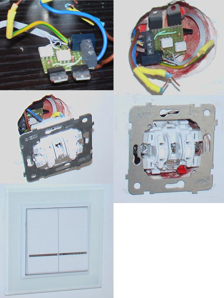
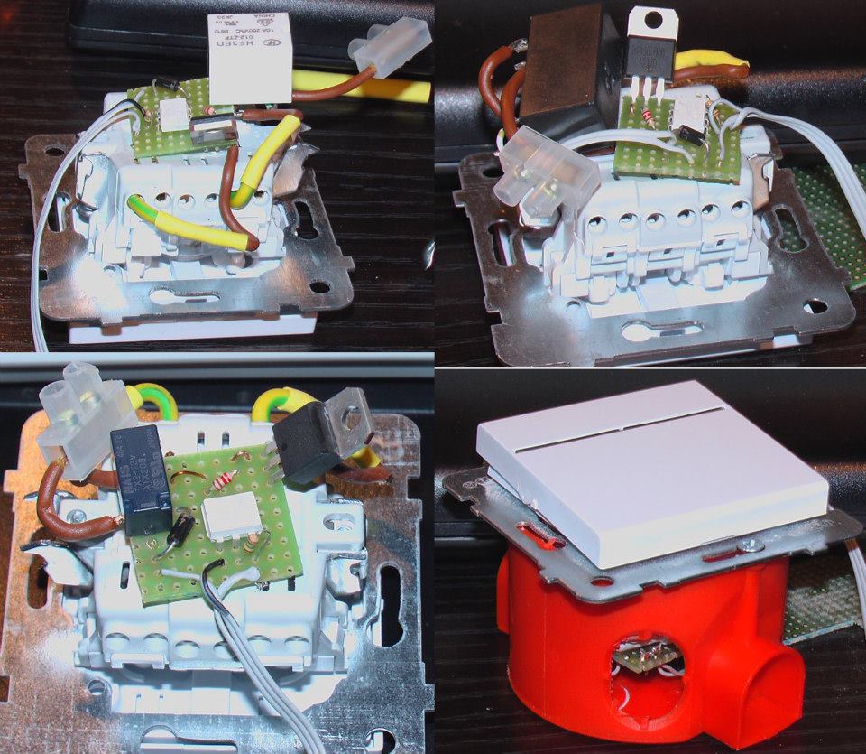
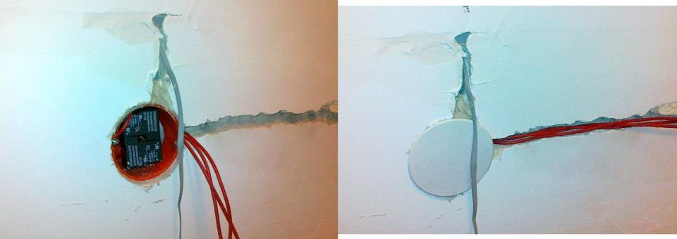
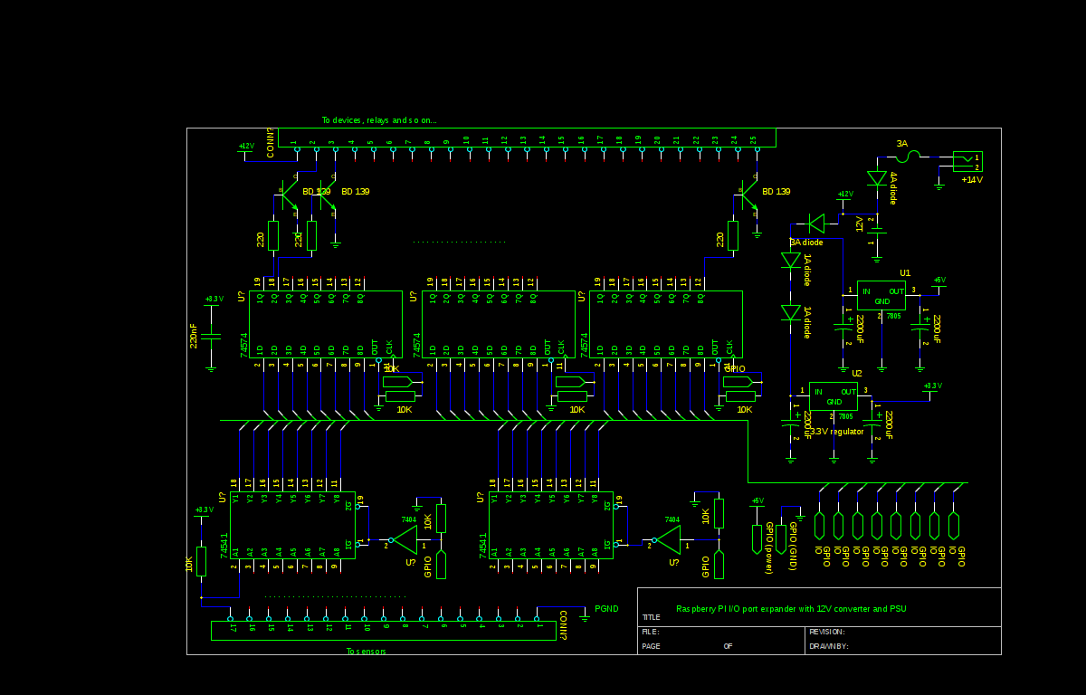
You have to make a port expander based on 8-bit D triggers (consolidation of output states) and three-state buffers of sensor states, in order to adjust Raspberry PI for initial requirements. Another important thing to do is to provide the possibility to control the home automation in a case of computer switch off or failure, or the possibility of an emergency control or non-blocking rest states of the executive circuits. These can be relays' NC contacts (in this case, cheap 30A relays). The relays and executive elements were placed as close to the control objects as possible (you may have to drill some boxes for the relays at sockets and the executive elements of lighting should be put in the box with a switch).
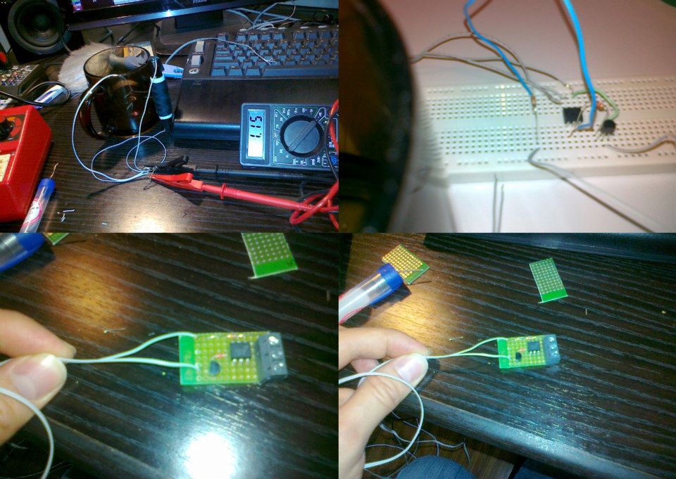
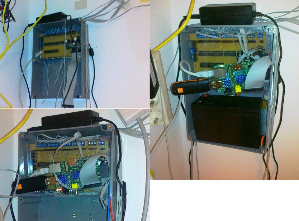
The pictures below show the process of controller tests (selection of relays and wires) and one of the boxes of relays before being filled.
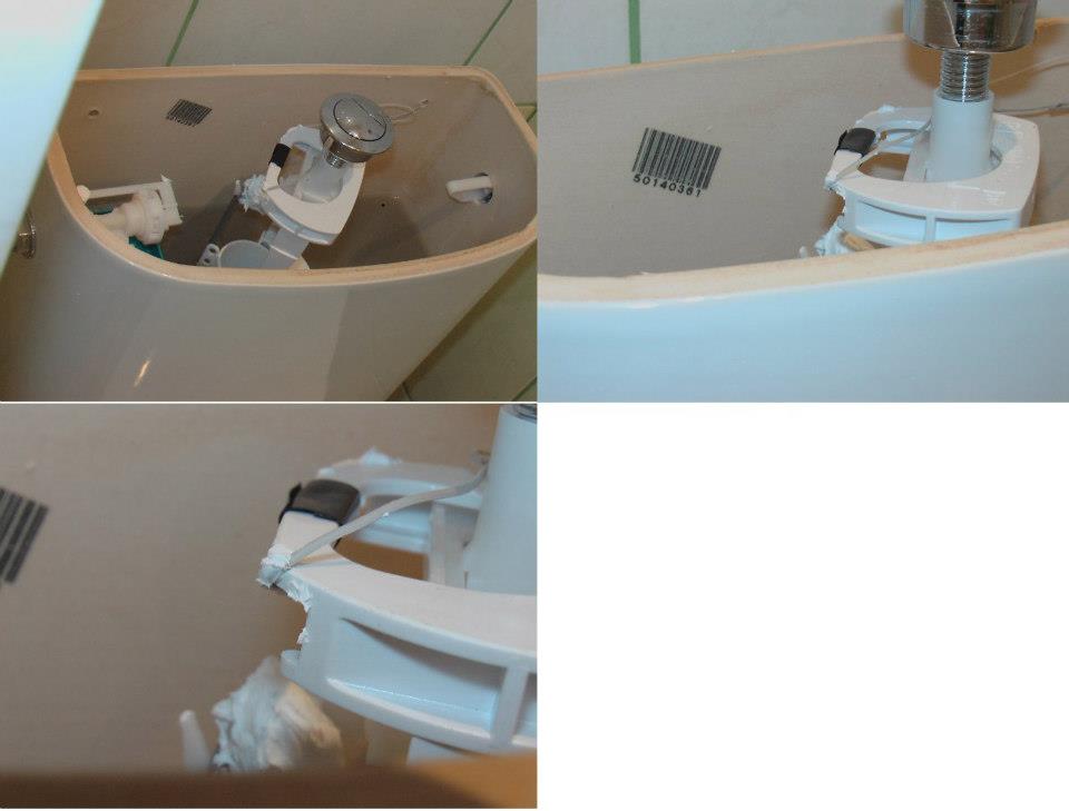
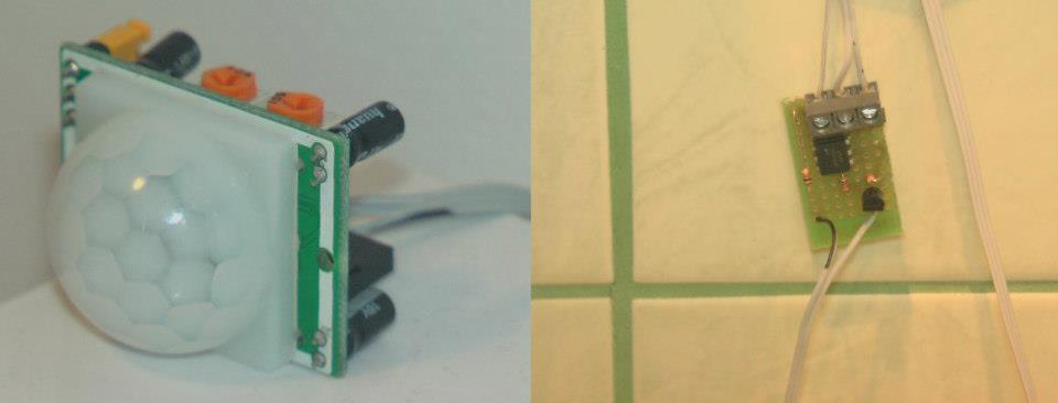
Another part of this construction consists of sensors. Most sensors were based on reed relays (relatively cheap and economic solution – low current consumption). As you can see in the pictures below, these sensors were put not only to the doors, but also to the toilet cistern.
Another important issue was to design flooding sensors. Experiments ended on adequately cut two-wire cables connected to the transistor which was connected to optocoupler (to isolate it from possible unwanted electrical circuit between the device and flooded electrical installation). In some rooms (due to the lack or rare using doors), you can install cheap motion sensors (PIR).
And the central part of the system: the computer connected to the port expander, which is linked with the power system (Raspberry PI is powered by GPIO). Additional functionality is using the GSM modem, thanks to which you can control electric installation via SMS and receive a SMS in extreme cases.

And video of short presentation of the system:
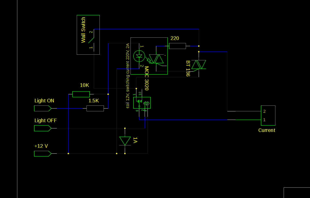
Schematic of the expander and wall switch controller.
Link to original thread - Dom inteligentny (automatyka domowa) za 500 pln na Raspberry PI