asking
Full Member level 5
Hello,
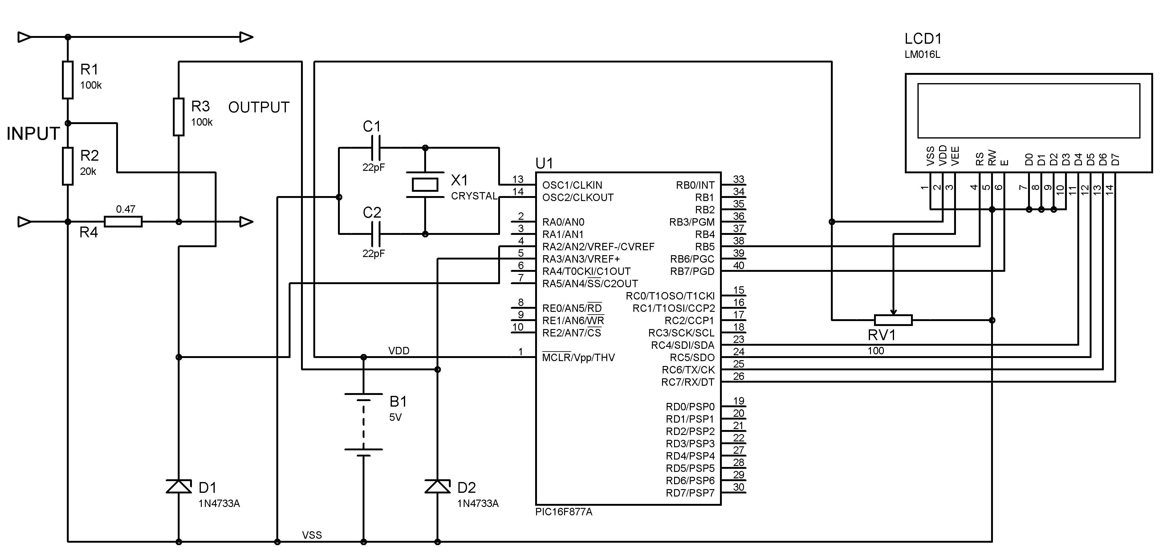
I tried to made Digital Voltmeter and Ammeter
Here's the Circuit diagram
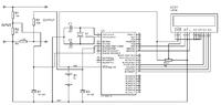
Problem's M Facing:-
1) Voltage and Current both values fluctuating..constantly...
2) Not measuring the voltage or currrent...values...
Question...
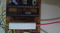
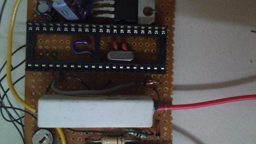
Can we place crystal below the microncontroller ? will it affect its operation ? (photo below)
Please help.....
I tried to made Digital Voltmeter and Ammeter
Here's the Circuit diagram
Problem's M Facing:-
1) Voltage and Current both values fluctuating..constantly...
2) Not measuring the voltage or currrent...values...
Question...
Can we place crystal below the microncontroller ? will it affect its operation ? (photo below)
Please help.....
Code:
// LCD module connections
sbit LCD_RS at RB5_bit;
sbit LCD_EN at RB7_bit;
sbit LCD_D4 at RC4_bit;
sbit LCD_D5 at RC5_bit;
sbit LCD_D6 at RC6_bit;
sbit LCD_D7 at RC7_bit;
sbit LCD_RS_Direction at TRISB5_bit;
sbit LCD_EN_Direction at TRISB7_bit;
sbit LCD_D4_Direction at TRISC4_bit;
sbit LCD_D5_Direction at TRISC5_bit;
sbit LCD_D6_Direction at TRISC6_bit;
sbit LCD_D7_Direction at TRISC7_bit;
// End LCD module connections
unsigned int v,vp,ip,i,volt1,current1, PWR;
char look(int a)
{
switch(a)
{
case 0:
return '0';
case 1:
return '1';
case 2:
return '2';
case 3:
return '3';
case 4:
return '4';
case 5:
return '5';
case 6:
return '6';
case 7:
return '7';
case 8:
return '8';
case 9:
return '9';
default:
return '.';
}
}
void main()
{
char *volt = "00.0";
char *current = "0.00";
TRISA = 0xFF;
volt1 = volt;
current1 = current;
Lcd_Init();
Lcd_Cmd(_LCD_CLEAR);
Lcd_Cmd(_LCD_CURSOR_OFF);
do
{
ADCON1 = 0x00;
v = ADC_Read(2);
i = ADC_Read(3);
i = (i*4.89)/0.47;
v = ((v*4.89)/20)*120;
if(v!=vp || i!=ip )
Lcd_Cmd(_LCD_CLEAR);
vp = v;
ip = i;
PWR = v*i;
volt[0] = look(v/10000);
volt[1] = look((v/1000)%10);
volt[3] = look((v/100)%10);
Lcd_Out(1,1,"V = ");
Lcd_Out(1,5,volt);
Lcd_Out(1,9,"V");
Lcd_Out(1,11,"POWER");
current[0] = look(i/1000);
current[2] = look((i/100)%10);
current[3] = look((i/10)%10);
Lcd_Out(2,1,"A = ");
Lcd_Out(2,5,current);
Lcd_Out(2,9,"A");
Lcd_Out(2,1,"A = ");
Lcd_Out(2,11,"hello");
Lcd_Out(2,16,"W");
Delay_ms(300);
} while(1);
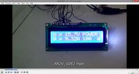
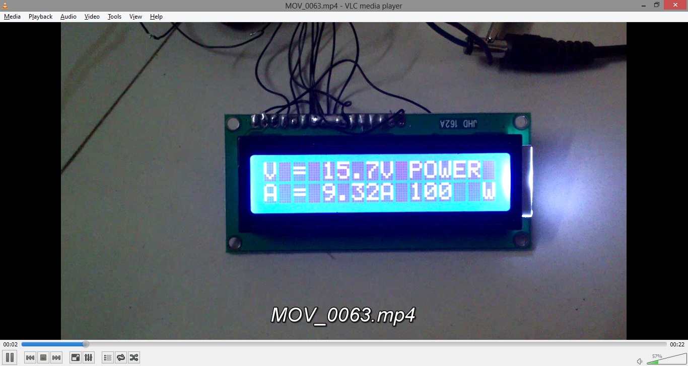
}") so finally now its working there's little calibration needed as the Resistors are not exact there always exist little difference in ohms..which makes error of 0.2V in this voltmeter/ammeter.
so finally now its working there's little calibration needed as the Resistors are not exact there always exist little difference in ohms..which makes error of 0.2V in this voltmeter/ammeter.