iamyuchenjie
Junior Member level 1
Solved (Cadence)What‘s wrong with the simulation result of the very basic RC circuit
Hallo,
I'm an EE student from TU Dresden.
Today I try to simulate some very basic RC circuits. (In spectre of Cadence 5141)
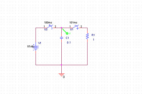
I am totally confused with the results. For example, I drew a very basic source-free RC serial circuit and try to find it's transient response. The circuit is as follow:

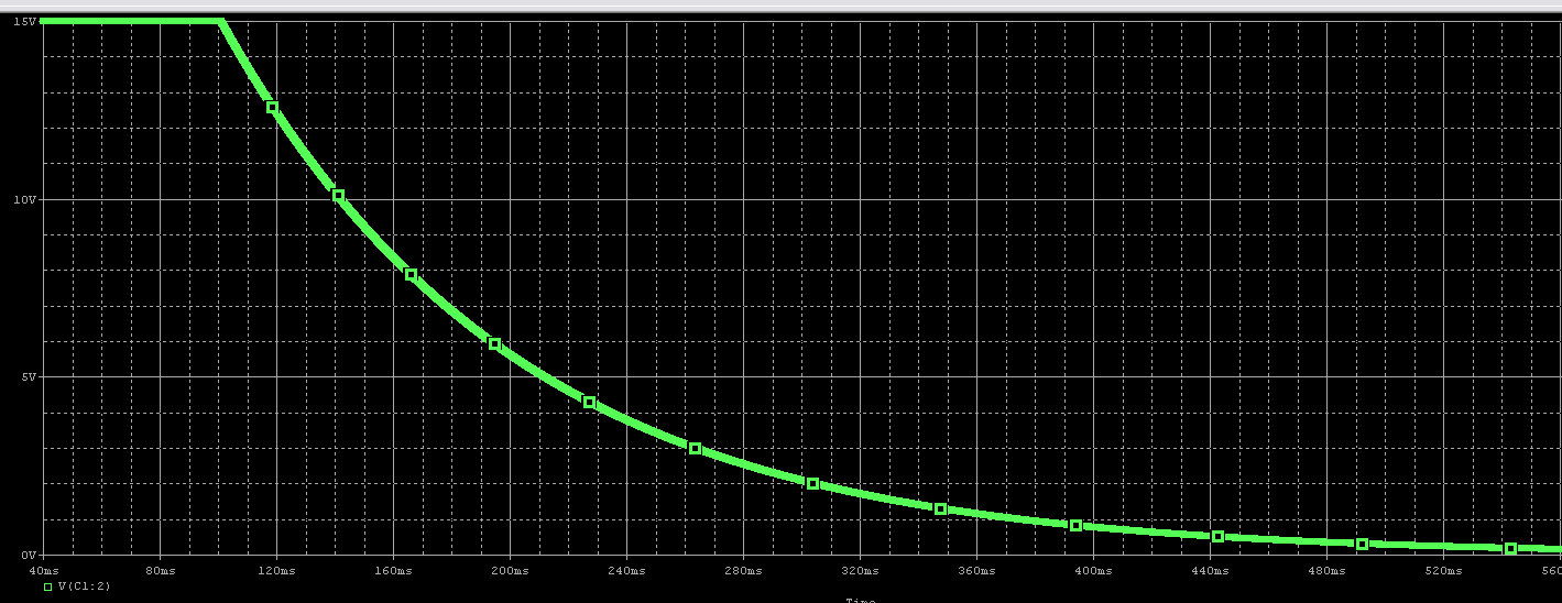
But the simulation result is that: the voltage of net3 start from (time 0 ) is 12.5V, instead of the initial condition value I set15V?

And I also try some other circuits with cap. but all the result is not right according to my understanding. I asked in the edabord, but no reply up to now.
Do you know why? I think the cap from the analoglib (Cadence build-in lib)is the ideal one, isn't it?
Or can u simulate it for me? Just 5 minutes is quite enough I think.
Really thank you!
--------------------------------------------------------------------------------
Hallo,
I'm an EE student from TU Dresden.
Today I try to simulate some very basic RC circuits. (In spectre of Cadence 5141)
I am totally confused with the results. For example, I drew a very basic source-free RC serial circuit and try to find it's transient response. The circuit is as follow:
But the simulation result is that: the voltage of net3 start from (time 0 ) is 12.5V, instead of the initial condition value I set15V?
And I also try some other circuits with cap. but all the result is not right according to my understanding. I asked in the edabord, but no reply up to now.
Do you know why? I think the cap from the analoglib (Cadence build-in lib)is the ideal one, isn't it?
Or can u simulate it for me? Just 5 minutes is quite enough I think.
Really thank you!
--------------------------------------------------------------------------------
Last edited: