karthick89
Newbie level 3
Friends,
my project: speed control of BLDC motor (square wave BLDC)...
my motor(load) specifications are: 24VDC(for inverter) 0.25HP 3000RPM and by calculations it shows current rating will be 8Amp
so the inverter should be designed for this specifications...
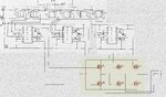
with the help of datasheet i designed the mosfet gate driver circuit, i have attached my circuit diagram here...
i have soldered this circuit in board....
for gate pulses, i used arm processor, 120 deg mode, given in correct sequence...
when i checked this circuit with just resistance load 1k ohm, the inverter output was step wave, only 10V peak to peak,
whatever input given to inverter, i got only 10V not exceeding it..
when i connected motor to this circuit, motor started at very less speed, and after few seconds, mosfet got burnt..
i checked this forum for the circuit, i found many corrections in my circuit....
so, i attached what i did in my circuit
friends, please guide me in solving my problem...
my project: speed control of BLDC motor (square wave BLDC)...
my motor(load) specifications are: 24VDC(for inverter) 0.25HP 3000RPM and by calculations it shows current rating will be 8Amp
so the inverter should be designed for this specifications...
with the help of datasheet i designed the mosfet gate driver circuit, i have attached my circuit diagram here...
i have soldered this circuit in board....
for gate pulses, i used arm processor, 120 deg mode, given in correct sequence...
when i checked this circuit with just resistance load 1k ohm, the inverter output was step wave, only 10V peak to peak,
whatever input given to inverter, i got only 10V not exceeding it..
when i connected motor to this circuit, motor started at very less speed, and after few seconds, mosfet got burnt..
i checked this forum for the circuit, i found many corrections in my circuit....
so, i attached what i did in my circuit
friends, please guide me in solving my problem...
Attachments
Last edited: