Continue to Site

Welcome to EDAboard.com

Welcome to our site! EDAboard.com is an international Electronics Discussion Forum focused on EDA software, circuits, schematics, books, theory, papers, asic, pld, 8051, DSP, Network, RF, Analog Design, PCB, Service Manuals... and a whole lot more! To participate you need to register. Registration is free. Click here to register now.

Trading voltage for current

Status
Not open for further replies.

electronpower03

Newbie level 6
Joined
Jan 22, 2013
Messages
14
Helped
0
Reputation
0
Reaction score
0
Trophy points
1,281
Activity points
1,427
Hey all,

Since power=IV, is it possible to reduce voltage to increase current ( well of course, power being constant)?

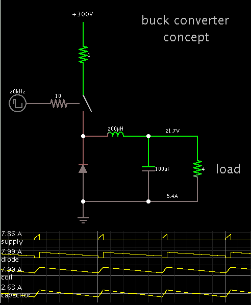
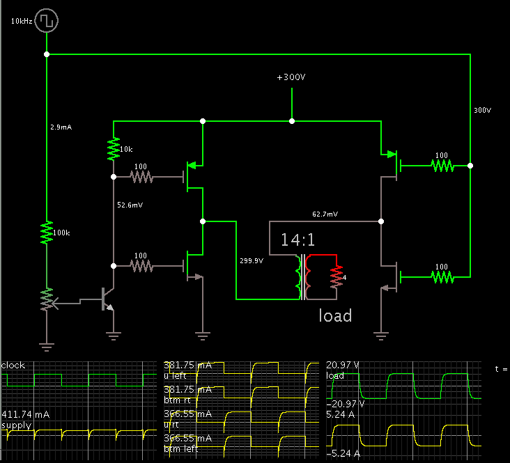
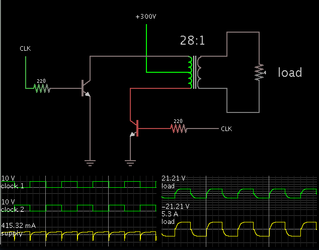
For example, a dc-dc converter has an output of about 300v at 0.4A, is it posible to reduce the 300v to get 20v at 5A?

If possible, how can this be achieved practically? Any circuit/ components, please?


Thanks for your responses!

Regards!
 

this is a common technique, that technique is a converter. dc to dc means its taking a voltage/current and converting it to a different voltage /current, with the restriction being power , and efficiency

it seems a bit silly though to use a converter on the output of a converter. but if you have multiple circuits running off that converter i could see it being required. besides using a converter you could look at regulators, regulators usually do not have such high current ratings though. for 5A loading id recommend a another voltage converter( which typically use an inductor or transformer).

-Pb


Thanks for you response!

So if I hook up the 300v at 0.4A to a buck converter, I should be able to get 20v at 5A?

Convening regulators, I thought their level of hysteresis is too high to be useful here? i.e instead of trading voltage for current, don't they wast it?

In sum, since you're recommending a conveter, i guess looking for a step down converter at TI or equivalent should solve the problem, right?


- Electronpower03
 

for your high current consumption yes id recommend a converter over a regulator(doubt you could find a regulator to handle such a large input voltage anyways), as far as efficiency yes regulators are less efficient, but are simpler to work with, and less noisy, and smaller footprint. You have a power source of 120Watts, your output requirement is 100Watts, requiring an efficiency of 84%, very doable. just make sure you dont use 70% efficiency converters and you will be good.
-Pb
 
To use a buck converter, your 300V supply must provide a burst of 8 amps at a duty cycle of 8 percent or so.


If your supply can only provide 0.4 A max, then you need to consider a transformer-based topology. Such as a flyback.

If efficiency is a chief concern, then chop the 300V through an H-bridge to a transformer.
 
There are a lot of "ready to use" solutions.
One example is here:
**broken link removed**

This is a cheap 230 AC power supply with 24V 5A output.
The clue is , that in fact it is a DC->DC converter as one can see on the block diagram.
300V-20V converter.jpg
At first 230V AC is rectified to 310 V DC (the peak value of 230V rms sine ).
One can simply apply 300VDC at the input (instead of 230V AC) and get isolated 24V/5A at the output.
The input /output separation can be remved if necessary, by simple connection of + or - from the input with the + or - at the output.
 
for your high current consumption yes id recommend a converter over a regulator(doubt you could find a regulator to handle such a large input voltage anyways), as far as efficiency yes regulators are less efficient, but are simpler to work with, and less noisy, and smaller footprint. You have a power source of 120Watts, your output requirement is 100Watts, requiring an efficiency of 84%, very doable. just make sure you dont use 70% efficiency converters and you will be good.
-Pb


Thanks!

Well, I found a converter at Vicor that should be able to do the job. I could use that or try some of the ideas below.

One problem though, I have yet to achieve the 300v. I've been able to get about 50v from a 5v source using a 557 and TIP122 as switch....

I noticed that when I replaced the TIP122 with say a 337 or an 2n2222, the output voltage was no more than 30. So, the TIP 122 is progress (most likely because of its darlington characteristics).....So any ideas about a transistor that can switch better for higher voltage? Say, some other more powerful darlington?

Is there a method I'm not applying?

Thanks!

- - - Updated - - -

To use a buck converter, your 300V supply must provide a burst of 8 amps at a duty cycle of 8 percent or so.


If your supply can only provide 0.4 A max, then you need to consider a transformer-based topology. Such as a flyback.

If efficiency is a chief concern, then chop the 300V through an H-bridge to a transformer.

Hey thanks for the post.

Do you have a schematic for the H-bridge--transformer method?
 

Hey thanks for the post.

Do you have a schematic for the H-bridge--transformer method?

Here is a bare-bones version, to illustrate how it would take 300 V at 410mA, and step it down to 20V at 5A.

Screenshot:


Naturally you would convert the output of the secondary to DC with diodes and a smoothing capacitor.

A real version would need more effort to make it work. For one thing, to make the clock circuit provide 300V, so as to turn off the upper right P-mos.

The transformer itself might need to be custom made.


Thanks!

I'll let yo know how it goes.
 

There is also an option which uses few components than the H-bridge. A half-bridge driving a step-down transformer which has a center-tapped primary:


The clock signals alternately turn on the transistors/ mosfets.
 

There is also an option which uses few components than the H-bridge. A half-bridge driving a step-down transformer which has a center-tapped primary:


The clock signals alternately turn on the transistors/ mosfets.

Ok.


I've got one more Q: say I got a power source of D.C. 5v at 0.5A . Please, how to I change it to AC?

I was thinking the 555 timer .....not sure it worked...maybe the chip was fried.

Are there any ICs or a circuits to convert the 5v D.C. to AC?

Thanks!
 

One problem though, I have yet to achieve the 300v. I've been able to get about 50v from a 5v source using a 557 and TIP122 as switch....

I noticed that when I replaced the TIP122 with say a 337 or an 2n2222, the output voltage was no more than 30. So, the TIP 122 is progress (most likely because of its darlington characteristics).....So any ideas about a transistor that can switch better for higher voltage? Say, some other more powerful darlington?

its not really clear to me whether you are trying to down-convert 300v to 5v or the other way around. In either case, using TIP122/ 557/ 2N2222 to switch 300v is not a good idea, since the Vce breakdown of these devices is typically < 100v at best.
 

its not really clear to me whether you are trying to down-convert 300v to 5v or the other way around. In either case, using TIP122/ 557/ 2N2222 to switch 300v is not a good idea, since the Vce breakdown of these devices is typically < 100v at best.


I apologize for the confusion.

What I meant is I wanted to up convert 5v to 300v. I said I've been able to convert 5v to 50v using the transistors I named.

I was thinking of converting 5 to 300, then to 20 for the 20 at 5A.


So, my Q was: is there a better transistor/method to get 300?

- - - Updated - - -

The H-bridge is the classic method:


The bias currents are adjusted to provide the desired amount of current to the load.


Could you please explain the 60Hz? Does it mean I have to input 60hz into the circuit or is that the AC output, because I thought the AC output is the R load.
 

If you want 20V output, you would convert 5V to 20V directly, rather than taking the detour over 300 V.

A large voltage ratio demands for a transformer based converter if reasonable efficiency is intended. This is due to the fact that switching losses of non-transformer buck or boost converter are proportional to maximum V * maximum I.
 

Could you please explain the 60Hz? Does it mean I have to input 60hz into the circuit or is that the AC output, because I thought the AC output is the R load.

The 60 Hz is in the control pulses or clock pulses. These come from an oscillator (or astable multivibrator) at low current.

The DC supply provides the load current. The H-bridge switches this current back and forth through the load, at the same frequency as the clock frequency.
 

The 60 Hz is in the control pulses or clock pulses. These come from an oscillator (or astable multivibrator) at low current.

The DC supply provides the load current. The H-bridge switches this current back and forth through the load, at the same frequency as the clock frequency.


Ah, the experiment didn't work.

The voltage dropped down to 0.5 thereabout. Output current was 0.2A

My objective was to increase the current of the 5v at 0.5A source.

According to this link:

https://www.ehow.com/how_8780713_increase-amperage-capacitors-diodes.html


It says AC current can be increase using capacitors. Thats why I wanted to convert the 5v source to AC.


First off, is what the ehow page says correct?

If not, whats the solution.


ultimately, if the AC current increase method doesn't work, then maybe the up-down conversion method might.

ideas, please?
 

You initial posts seems to be aware of the conservation of energy aspect, you have e.g. 300V/0.4 A (120 W) and intend to convert it to 20V/5A (100 W). 83 % efficiency should be feasible.

Is "increasing the current" another word for over-unity efficiency?
 

You initial posts seems to be aware of the conservation of energy aspect, you have e.g. 300V/0.4 A (120 W) and intend to convert it to 20V/5A (100 W). 83 % efficiency should be feasible.

Is "increasing the current" another word for over-unity efficiency?


I'm not sure I know what you mean by over-unity efficiency.

Let explain what I'm trying to do:


I want to conduct an experiment: " "transforming" a dc power source"...

Say you have a DC source-- 5v/0.5, 5v/1.5A, a 9v/1A battery, 1.5v/1A battery etc....any DC source . How do you "transform" it? The idea is to transform that source to about a 100 watts-- the 20, 5A I talked about earlier.

Now, here are my propositions to achieving this:

1) Step up the, say, 9v source to 300v ( I'm at least 50٪ sure this is possible because I've been able to step up 5v to to about 60 without any more than 100mA "lost"!), then step it down to 20v at 5A-- like my first post asked.

2) Convert the DC source to AC, then back to Dc. Based on the premise of the content of the above "ehow" page, and say we have, 4.9v converted AC voltage (according to Bradtherad's snapshot help), using I(t) = Vs/R*(e-t/RC), we can calculate the value of I with time to be approximately the value of the input 4.9v-- if R and C are assumed 1 ohm and 2000uF respectively.

I also observed that I with time cannot get past the value of the input voltage....positively, that is! :) (well, based on the above assumptions). It in fact starts dropping with time....significantly from about 300us!

So, say we get 4.9v AC at 4.9A, this can be fed to a multiplier and eventually rectified to give the desired 100watts (hopefully the amperage isn't reduced drastically!)


Those are my ideas, guys. What do you think? Possible? The first one more feasible that the second? :)
 

1.

If you want 20V at 5A, then you must provide 5V at 20A (not counting losses due to inefficiency). In other words, to get 100W out, you must put 100W in.

Small batteries cannot provide that many watts.
I believe a string of 4 D batteries might be able to provide over 10 A at 5V.

2.

The Ehow page has a misstatement or two.
You can get more AC current through a capacitor by increasing its Farad value, but for that to happen, the AC source needs to be able to provide that much current.

As for DC, the capacitor blocks DC as soon as it has charged sufficiently.

It claims that a diode will increase current. This works in the sense that an AC waveform has a zero net average value..., however when you take one half of it (by rectifying it), then it gives you a waveform which can do things that AC cannot. You're taking either the positive or negative power and that is 50 percent of the original.
 

Status
Not open for further replies.

Similar threads

Part and Inventory Search

Welcome to EDABoard.com

Sponsor

Back
Top