Continue to Site

Welcome to EDAboard.com

Welcome to our site! EDAboard.com is an international Electronics Discussion Forum focused on EDA software, circuits, schematics, books, theory, papers, asic, pld, 8051, DSP, Network, RF, Analog Design, PCB, Service Manuals... and a whole lot more! To participate you need to register. Registration is free. Click here to register now.

Please tell me working of 'simple FM transmitter' circuit.

Status
Not open for further replies.

Shan31

Newbie level 4
Joined
Jan 19, 2013
Messages
5
Helped
0
Reputation
0
Reaction score
0
Trophy points
1,281
Location
Ahmednagar, India
Activity points
1,316
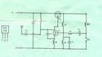
I recently bought a 'simple FM transmitter kit. I've assembled and soldered the circuit. It totally works. It can transmit the signal up to 300 m. I have to submit it in my school as my electronics project. But I'm unknown about the working of the components and the circuit. I searched all over the internet but I couldn't find the circuit resembling with mine one. Please help. The circuit contains only one transistor.

Following components were provided with the kit:

Resistors:
R1 = 10K
R2 = 15K
R3, R4 = 4K7
R5 = 47E

Capacitors:
C1, C5 = 0.01 (10KPF) (103)
C2 = 10PF
C3 = 0.001KPF
C4 = 2.2/6V

Miscellaneous:
Transistor = BEL548
Mic = 2 pin cond. mic
Inductor coil = 4 Turns
Trimmer = 2....22pF
Supply = 9V
Antenna = 70cm Antenna

Thanks in advance. All kind of help is appreciated. :roll:
you may contact me here : shantanutonde@gmail.com
 

hi there
welcome to the forums

well without a circuit to look at, we cant tell you anything about the project
post a schematic, or at least post a link to a www site that has the circuit and description

Dave
 

Here is the circuit diagram I used.
 

Attachments

  • scan0064.jpg
    scan0064.jpg
    798.3 KB · Views: 138

Thank you guys. Thanks for helping me. Isn't there anyone in this world who knows 'how a FM transmitter circuit works???'. Anyway, can somebody tell me, how can I delete my account on this forum???
 
Last edited:

Nice reference Keith :) thanks
need to spend some time reading through that

as far as the circuit posted above goes, I cant see it operating too well (at all) with a trimcap in the collector cct

cheers
Dave
 

Here is the circuit diagram I used.
Just to clarify: TR1 on the diagram is the variable capacitor, connected between Q1's collector and (+)VE.

Anyway, here's how it works:
Q1 is a simple oscillator. R2, R4 and R5 set the Q-point. C1 effectively shorts the base to ground at RF so that Q1 acts as a common-base amplifier.

Q1's collector is loaded with a tuned circuit made of L1 and the parallel combination of C2 and the variable capacitor. C2 also provides feedback from the collector to the emitter, to sustain the oscillation. The output of the oscillator is coupled to the antenna through C3.

R1 provides bias voltage to the microphone, and the audio signal from the microphone is coupled to Q1's base through C5 and R3. Note that C1 is high impedance at audio frequencies so it does not short the audio signal to ground.

Now comes the hard part - understanding how modulating Q1's base voltage modulates the oscillator's frequency....

The important thing to know is that any transistor has some capacitance between it's base and collector, and that capacitance changes depending on the voltage between base and collector.

This means that the audio signal applied to Q1's base modulates Q1's collector-base capacitance. But that capacitance is in parallel with TR1 (your tuning capacitor), so the oscillator frequency is modulated as well.

The change in collector-base capacitance with voltage is small, and the audio voltage applied to the base is also small, so the change in total tuning capacitance is very small. However, full strength modulation for an FM transmitter only requires the frequency to be modulated by about 0.1%. Even if you only get 0.01% modulation, the signal will still be clearly heard at the receiver, although it will be softer than normal.

- - - Updated - - -

as far as the circuit posted above goes, I cant see it operating too well (at all) with a trimcap in the collector cct
Most simple FM transmitter/bug circuits work like that with no problem. E.g. here's another (even simpler) example: https://www.buildcircuit.com/simple-steps-for-making-fm-transmitter/.
 
Thanks.. That really helped me..

- - - Updated - - -

I wasn't really thinking to leave the forum. I said it just to get answers more quickly. And it worked. Sorry.
 

Status
Not open for further replies.

Part and Inventory Search

Welcome to EDABoard.com

Sponsor

Back
Top