Continue to Site

Welcome to EDAboard.com

Welcome to our site! EDAboard.com is an international Electronics Discussion Forum focused on EDA software, circuits, schematics, books, theory, papers, asic, pld, 8051, DSP, Network, RF, Analog Design, PCB, Service Manuals... and a whole lot more! To participate you need to register. Registration is free. Click here to register now.

High Voltage, low current power supply.

Status
Not open for further replies.

certino

Junior Member level 1
Joined
Jan 1, 2013
Messages
18
Helped
0
Reputation
0
Reaction score
0
Trophy points
1,281
Activity points
1,412
Hello all,

I am testing avalanche photodiode and I need power supply for breakdown voltage.. First I did circuit based on NE555, but precision was horrible (about 2 V ripple, I need very stable voltage). Next I found an118 datasheet from linear. In this sheet is circuit (page 10, figure 24). Author wrote about 2mV ripple so I built this circuit but still I have unstable voltage (now ripple about 0.5 V). Where is problem ?
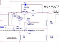
 

Is your problem ripple, noise or instability? Ripple due to switching should be removed by the linear regulator section.

The linear regulator will be very sensitive to what is on the programming input - 5mV on there will translate to 0.5V on the output. So, you need to make sure the program voltage is very clean.

A quick and easy APD power supply for testing is a box of cheap PP3 batteries with a pot on the last one. Add a couple of decoupling capacitors and stack the batteries to get the right voltage.

Keith.
 

Problem is with ripple. Example - If I set 172.5 V I have between 172.2 and 172.7
My ref voltage consist of REF02, operation amplifier and potentiometer.
Maybe do You have any tested circuit for ref voltage in range 0-3 V ?
 

This is a circuit I have used a long time ago with no problems. The high voltage was generated with an LM2578 with the linear regulator to set the actual voltage lower (and ripple free). It worked well but needs a stable, clean control voltage.


It wasn't designed with any long term stability or temperature stability in mind. The control voltage was ramped until breakdown was detected then reduced by a small amount. This was done everytime the APD was used and when any measurements were made, so it never needed to be stable for more than a few seconds.

Keith.
 

Great, thank You very much. One question: range for control and range for input supply ?
 

I must admit I am not sure (I designed it over 20 years ago!) but it would be around 3V maximum for the control voltage. I think the maximum output voltage was around 250V (which would correspond to 3V control voltage, looking at the resistors). The LM2578 was generating 270V. You can obviously tweek the resistor values to adjust the voltages. There was 10nF on the output at the APD.

Keith
 

Status
Not open for further replies.

Similar threads

Part and Inventory Search

Welcome to EDABoard.com

Sponsor

Back
Top