Continue to Site

Welcome to EDAboard.com

Welcome to our site! EDAboard.com is an international Electronics Discussion Forum focused on EDA software, circuits, schematics, books, theory, papers, asic, pld, 8051, DSP, Network, RF, Analog Design, PCB, Service Manuals... and a whole lot more! To participate you need to register. Registration is free. Click here to register now.

interfacing LCD mdule with PIC 16f877a

Status
Not open for further replies.

chalani0088

Junior Member level 3
Joined
Jun 19, 2012
Messages
27
Helped
0
Reputation
0
Reaction score
0
Trophy points
1,281
Activity points
1,562
Hi , I want to interface LCD module with PIC 16f877a

I used the following code and used Hitech C

my main program is,

#include <htc.h>
#include "lcd.h"

void
main(void)
{
lcd_init();
lcd_goto(0); // select first line
lcd_puts("12345678");
lcd_goto(0x40); // Select second line
lcd_puts("Hello world");

for(;;);
}

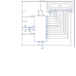
and I have attached the LCD source code and also the circuit I used,

But it didn't display anything and showed black rectangulars, didnt show cursor either/

Can anybody help me

thnk you
 

Attachments

  • lcd.txt
    2.4 KB · Views: 124
  • circuit.png
    circuit.png
    54.7 KB · Views: 145

I don't know C so I will restrict my comments to the circuit. You don't need the 10uF capacitor and it would be better to remove it and instead of connecting the Vee line to ground it would be better to have a 5K pot. Have you set the configuration word correctly? that is HS mode with the watchdog off and the power on timer on. In the circuit you have a 12Mhz crystal and the software it is 4 Mhz.
 
Schematic looks okey. But the schematic and your code doesn't match.
1. Frequency mentioned in schematic is 12Mhz. But in code, it is 4Mhz.
2. LCD pins RS, R/W, EN and Data D0 - D7 pins are connected to RA0, RA1, RA2 , RB0-RB7 pins in schematic. change the code as connections in schematic.

Change the following and load the hex in your microcontroller.

Best wishes :)
 
Give some delay after the lcd_init() function.
This gives some time for the LCD to initialize.
About 10ms-50ms would be enough.

This us usually the problem when we see the LCD fully lit up with all black rectangles.
 
thank you all for supporting me. Yes it is the problem with frequencies. oscillator frequency didn't match with the programmed frequency. I corrected the errors in my circuit. Now its functioning well

Regards
Chalani
 

Status
Not open for further replies.

Part and Inventory Search

Welcome to EDABoard.com

Sponsor

Back
Top