Continue to Site

Welcome to EDAboard.com

Welcome to our site! EDAboard.com is an international Electronics Discussion Forum focused on EDA software, circuits, schematics, books, theory, papers, asic, pld, 8051, DSP, Network, RF, Analog Design, PCB, Service Manuals... and a whole lot more! To participate you need to register. Registration is free. Click here to register now.

"ADS Momentum port placement issue"

Status
Not open for further replies.

adnan012

Advanced Member level 1
Joined
Oct 6, 2006
Messages
468
Helped
2
Reputation
4
Reaction score
2
Trophy points
1,298
Activity points
4,923
hi,

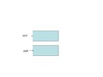
I want to simulate a micro stripe line of a given length in ADS Momentum. As shown in the attached figure , first i attached the 50 ohm port at the edge of the patch and performed simulation. Secondly i placed the port inside the structure not at the edge .Now the simulation result slightly differs from the first one. Which one is correct. What is the difference in calibrated ports and internal ports in ADS.
 

Attachments

  • 1.JPG
    1.JPG
    15.7 KB · Views: 93

Thanks for reply.
I have studied "Ports in Momentum" topic available on ADS website. I have also seen momentum examples. But i am still confused about the position/type of ports (internal or at the edge) when it involves any TRANSISTOR (LDMOS) at one side.
 

the position/type of ports (internal or at the edge) when it involves any TRANSISTOR (LDMOS) at one side.

Usually, you want to have port calibration enabled, for more accurate results. Port calibration is only possible when the port is on the edge (not inside) the polygon.
For transistor and other components, have a look at the documentation for "SMD" calibration type-
 

Status
Not open for further replies.

Part and Inventory Search

Welcome to EDABoard.com

Sponsor

Back
Top