Continue to Site

Welcome to EDAboard.com

Welcome to our site! EDAboard.com is an international Electronics Discussion Forum focused on EDA software, circuits, schematics, books, theory, papers, asic, pld, 8051, DSP, Network, RF, Analog Design, PCB, Service Manuals... and a whole lot more! To participate you need to register. Registration is free. Click here to register now.

Why S11 down at 0->0.5 GHz in WLAN antenna simulation

Status
Not open for further replies.

votientu

Member level 2
Joined
Oct 27, 2012
Messages
47
Helped
0
Reputation
0
Reaction score
0
Trophy points
1,286
Activity points
1,647
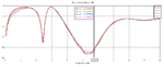
Hi, do you know why this S11 seems wrong at very low frequency, it increases from -15 to 0 in the band from 0 to 0.5 GHz,
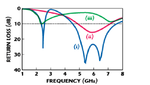
it would be still at 0 in this band like this picture ( I refer it in a paper).
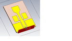
I use CST to simulate and the mode at port is Quasi-Tem, I use CPW-fed in my design, E at port is ok,
but impedance is 62 ohm, not 50 ohm like in that paper. Port dimenson is 4W*4h.

Thank you!
 

Attachments

  • 1.png
    1.png
    32.4 KB · Views: 110
  • 2.png
    2.png
    35.1 KB · Views: 108

I don't see a reasonable purpose to discuss characteristics of an unspecified antenna geometry. :-(
Technically, a low S11 number at low frequency requires a resistor built-in to the antenna, doesn't sound like a realistic design.
 

Thank FvM,
Here is my design, do you use CST ?
Please help me !
 

Attachments

  • cpw antenna.rar
    12.3 KB · Views: 67
  • 1.png
    1.png
    23.6 KB · Views: 104

Status
Not open for further replies.

Part and Inventory Search

Welcome to EDABoard.com

Sponsor

Back
Top