Continue to Site

Welcome to EDAboard.com

Welcome to our site! EDAboard.com is an international Electronics Discussion Forum focused on EDA software, circuits, schematics, books, theory, papers, asic, pld, 8051, DSP, Network, RF, Analog Design, PCB, Service Manuals... and a whole lot more! To participate you need to register. Registration is free. Click here to register now.

How can obtain higher efficeny on a boost smps

Status
Not open for further replies.

Vlad.

Full Member level 3
Joined
Jun 4, 2012
Messages
179
Helped
3
Reputation
6
Reaction score
4
Trophy points
1,298
Location
Bucharest/Romania
Activity points
2,568
I design a boost converter with uc3843+irf3205 to make 20v adjustable from 12v. now i have the efficeny about 82%, how can i make it up to 90%? who know some tricks for that?
 

Make sure you have minimized resistance through all components in switch-On cycle.

It may help if you raise the switching frequency (within limits).

Avoid driving the coil above its saturation current, or above its safe temp current.
 

What is the output power? What is the switching frequency?

For the MOSFET, you have three types of losses involved: conduction loss, switching loss and gate charge loss. To decrease conduction loss you need to use a MOSFET or a combination of MOSFETs will lower overall RDS(on). To reduce switching loss, you may decrease switching frequency. To reduce gate charge loss, use a MOSFET or a combination of MOSFETs that will give a lower gate charge. You can also reduce the frequency.

These are some ideas. I'm sure there are more.

Hope this helps.
Tahmid.
 

hey thanks for all you ideas. The maximum power estimated is 100w. the switching frrequency is about 90khz? is good or verry bad? the mosfet that I use is irf3205 but i have irz44z but is better first one. I use a toroid coil green+blue colored recover from and forward atx suply, i will try to use on the next tests and flyback transformer
 

Getting high efficiency generally requires you tabulate all the sources of power dissipation in the entire converter, and there are over a dozen sources to account for, and some are quite complicated to estimate. I'd recommend estimating losses due to the FET and diode using a procedure like **broken link removed**. If that can't explain most of your losses, then you should look at ESR in your inductor and capacitors, and in controller quiescent current.
 

What is the output power? What is the switching frequency?

For the MOSFET, you have three types of losses involved: conduction loss, switching loss and gate charge loss. To decrease conduction loss you need to use a MOSFET or a combination of MOSFETs will lower overall RDS(on). To reduce switching loss, you may decrease switching frequency. To reduce gate charge loss, use a MOSFET or a combination of MOSFETs that will give a lower gate charge. You can also reduce the frequency.

These are some ideas. I'm sure there are more.

Hope this helps.
Tahmid.

HI Thami.
I want 2 make a boost converter with more than 90% efficiency.Input Voltage 3.8 v to 4.6 v / 4 Amp.Output voltage need 10.5 to 11 v 800 mA. Please send me the diagram if you have.
:grin:
.
 

Do you plan on using dedicated boost converter chips? Or do you plan to make the converter using general purpose components?
 

HI Thami.
I want 2 make a boost converter with more than 90% efficiency.Input Voltage 3.8 v to 4.6 v / 4 Amp.Output voltage need 10.5 to 11 v 800 mA. Please send me the diagram if you have.
:grin:
.

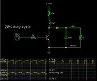
This is in reach, theoretically. Here is a screenshot of a simulation of a basic boost converter.


The .3 ohm resistor represents the fact that there will be some overall resistance in the power loop. You must keep this at a minimum if the project is going to succeed.

The coil and frequency values are flexible.

The transistor must endure 50 or 60 mA of bias current. It must be heavy duty. A mosfet could work but only if it will turn full on at a few volts supply.
 

Do you plan on using dedicated boost converter chips? Or do you plan to make the converter using general purpose components?

Dear Tahmid,
Thnx for your reply.There are many curcuit avalable in website.But they all are using some specal chip base.Wich is not avalable in INDIA normaly.It,s very difficult to buy all those.But if we go for some genaral component like using MOSFET, IC Like 555
etc. then its very easy to make it.I know that time efficeny level may decrease.But still i need it.Main pourpose for making LED driver.
 

I`m back, can somebody with experience in smps tell me what are advantages and dizavantages of bipolar power tranzistors(I have STW13009) and mosfet tranzistors in smps like boost? how can he influence the eficiency?
 

BJTs are very rarely used in SMPS anymore, because MOSFETs have lower conduction losses and are easy to drive at high frequencies. In applications with very high voltage or current and low frequencies, IGBTs are often used, but they are very different from BJTs.
 

hi do you have any boost converter circuit diagram.My requrement
voltage in min-3.8V to max 4.5V (4Amp)
out put min- 10.5 to max 10.8 (700 mA) 10 watt

if you have then please send me urgent. i need it dear
:grin:
 

hi do you have any boost converter circuit diagram.My requrement
voltage in min-3.8V to max 4.5V (4Amp)
out put min- 10.5 to max 10.8 (700 mA) 10 watt

My schematic in post #8 shows a simplified version. What's missing is the control module. This is usually an IC designed to switch a boost converter on and off, automatically adjusting the frequency and duty cycle, to provide your desired output volt level at the load.

I don't know the names of IC's which are best for a boost converter. It will either need to handle 5 amperes, or you'll need to make it control a mosfet/transistor which can handle the current.

There are several threads here which discuss boost converters. Or try an internet search.
 

Status
Not open for further replies.

Similar threads

Part and Inventory Search

Welcome to EDABoard.com

Sponsor

Back
Top