Continue to Site

Welcome to EDAboard.com

Welcome to our site! EDAboard.com is an international Electronics Discussion Forum focused on EDA software, circuits, schematics, books, theory, papers, asic, pld, 8051, DSP, Network, RF, Analog Design, PCB, Service Manuals... and a whole lot more! To participate you need to register. Registration is free. Click here to register now.

555 Timer output takes too long to go high after startup

Status
Not open for further replies.

browner87

Newbie level 4
Joined
Mar 14, 2009
Messages
5
Helped
0
Reputation
0
Reaction score
0
Trophy points
1,281
Activity points
1,327
I'm building a circuit and this is the basics of it:
After a brief delay after power-up, a latch goes from low to high and stays high until power-down.

On a more technical level:
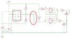
A 555 timer starts at power up. I feed its output into the NOT-R of a NOT-SR latch. I'll attach the circuit below.


Now, if I build just the 555 timer part and hook an LED (and resistor) to its output, it appears the output is immediately high after power-up, and then goes low after ~3 seconds as expected.
And if I build just the latch part, Q is high on power-up as expected (and will go low if I ground NOT-R).

The problem is, if I connect the output of the 555 timer to the NOT-R of the latch (the circled wire), Q is low and NOT-Q is high at power up. Unfortunately I don't have an oscilloscope lying around to check, but logic says to me that the output of the 555 timer is low for a couple nano or microseconds at startup which is enough to toggle the latch too soon.

Does anyone know how I can make the latch "wait" a couple milliseconds to let the timer power up? I'm sure a well-placed capacitor would fix it in a heartbeat, but I can't decide exactly where to put it to get the desired result.
 

Attachments

  • Circuit.png
    Circuit.png
    28.8 KB · Views: 129

I'm sure a well-placed capacitor would fix it in a heartbeat, but I can't decide exactly where to put it to get the desired result.

On the chance this is what you are talking about...

The screenshot shows simple ways to pull a line low or high after a delay of a few milliseconds. As you stated it uses a capacitor and resistor network.


The scope traces show that the capacitors hold their charge during brief lapses in power. This means they will take a second or two to discharge after power is removed.
 

That is why I'm using the 555 timer. This will be part of a brake light system on a car, and I need the circuit to reset within a few dozen milliseconds of losing power. When you hit the brakes, the circuit will cause a brief delay (but very specific, I need to time it accurate to 20ms or so), then turn on a MOSFET which will turn on the brake light. But if someone pulses the brakes, or uses their turn signal, I want the exact same delay again.
 

The capacitor and resistor values can be altered, depending on if you want quicker or slower action.

I tried to modify my schematics so that (a) the capacitors fall or rise within a 20 mS time frame, and (b) so that the recovery time is 90 mSec.


It's only a concept... an inexpensive way to delay the start of a 555 timed cycle.
It may not be what you are looking for.

If you need for both time periods to be adjustable, then it will work if you were to just use two 555 timers, to produce multiple staged time periods. When the first time delay ends, it triggers the second.
 

Thanks for the help, but this isn't what I need. I will need a time somewhere between 100 and 300ms and the person building it will decide that for themselves, but the circuit can't take more than 50ms or so to reset (at very most).

Is there maybe a way to make the 555 timer start with a low output and then after whatever time is decided by R1,R2, and C1 go high, instead of starting high and going low?
 

Is there maybe a way to make the 555 timer start with a low output and then after whatever time is decided by R1,R2, and C1 go high

I notice you have tried an unconventional connection or two at the 555 pins.
Starting from there...

I played with a component or two and came up with this.


The timing capacitor is removed.
After 20 mSec the output turns on and stays on until power is removed.

Recovery is very quick. Notice the circuit is able to operate again within 20mSec after power is removed.

The scope trace begins at the 'Reset', or blue vertical line. Notice that there was no glitch as the simulation began, resulting in unwanted high pulses.

Can't be certain if real components will perform the way you want. It's just an experimental concept.

- - - Updated - - -

Gotta back-pedal here.

Recovery requires that the capacitor discharge to ground through the clock connection. If it is switched, then the capacitor cannot discharge. It will not perform its delay function the next time power is applied.

Something else needs to be tried.

The 555 is versatile in this regard. With a bit more persuasion it could be made to perform the function you need.
 

This looks promising! I will look and see if I can get the timings I want from it. Could I just throw in a tie-down resistor from the supply to ground? Maybe I can use a transistor or something (P-Channel J-FET?) to tie the input to ground when power is lost...

EDIT: I'm going on the idea right now of a P-JFET between VCC and GND with gate tied to VCC. Can anyone suggest a part number? I'm not familiar with JFETs... :)
 
Last edited:

This looks promising! I will look and see if I can get the timings I want from it. Could I just throw in a tie-down resistor from the supply to ground? Maybe I can use a transistor or something (P-Channel J-FET?) to tie the input to ground when power is lost...

Yes, to restore quickly to a ready condition, you will need to discharge the capacitor quickly.

The 555 has a discharge pin which is normally used on the timing capacitor.
It also has a comparator, etc.
There are some novel circuits which make use of these, in other ways than we are accustomed to seeing for the 555.

Example link below. It may have a circuit that will lead to a solution for you.

**broken link removed**

EDIT: I'm going on the idea right now of a P-JFET between VCC and GND with gate tied to VCC. Can anyone suggest a part number? I'm not familiar with JFETs... :)

JFET's are not so common. I believe Radio Shack carried the 2N3819 N-type. The P-type appears to be 2N3820.

A mail-order house might carry 'house' brand unmarked JFET's.
 

This is an exceedingly helpful link! Thank you very much, I shall peruse it when I get a minute to see what I can uncover.

As for JFETs I typically buy off of eBay and they usually have almost any kind of electronic component for cheap. They have 10 2N3820's for $5. But you're right, they aren't very common and I'd rather stick to cheap, easily found parts since I'll be posting this circuit for people to replicate when it's done.

Thanks for the help guys, I'll post back soon when I've tried some of the circuits out!
 

Status
Not open for further replies.

Part and Inventory Search

Welcome to EDABoard.com

Sponsor

Back
Top