Continue to Site

Welcome to EDAboard.com

Welcome to our site! EDAboard.com is an international Electronics Discussion Forum focused on EDA software, circuits, schematics, books, theory, papers, asic, pld, 8051, DSP, Network, RF, Analog Design, PCB, Service Manuals... and a whole lot more! To participate you need to register. Registration is free. Click here to register now.

Switching power supply with variable output voltage?

Status
Not open for further replies.

Astrid

Full Member level 3
Joined
Jul 11, 2011
Messages
152
Helped
4
Reputation
8
Reaction score
3
Trophy points
1,298
Activity points
2,492
Hello , I have idea make switching power supply with variable output voltage , for example 2-50V 100W.
For simplicity, let's say we used TOP271 from TOPSwitch family.
On picture is design for 50V 3A PS designet with TOP271, with whom I replaced one winding 12V ​​from an external source .If in to voltage divider place variable resistor will be easy change output voltage.
The question is how to deal with transformer to achieve the widest possible voltage regulation and power transmission?
Do you know of a sample solution or appnote on a similar switch mode power supply?
The fact that components must be designed for the maximum voltage (50V) and max current (say 12A) perhaps goes without saying
TOP.png
 

The question is how to deal with transformer to achieve the widest possible voltage regulation and power transmission?
Do you know of a sample solution or appnote on a similar switch mode power supply?
The fact that components must be designed for the maximum voltage (50V) and max current (say 12A) perhaps goes without saying

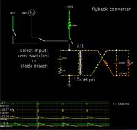
I am running a simulation of a simple flyback.

You will need to design your transformer carefully, to get the range of output you desire.

My simulation shows a windings ratio around 8:1 or 12:1 should work. From there you can vary the frequency and duty cycle to get a desired output.

If it is 8:1 then you will run it at a few percent duty cycle, to get 2V out.

It should not be 100:1. This would require enormous current flows in the secondary when you want maximum power. Even if you make the duty cycle 90% to get 50V out, there would only be 10% of the time period for the secondary to conduct. Large current flows will be needed... several tens of amperes.

Even as it is, you'll have 10 or 20 A going through the secondary when drawing maximum volts and maximum amps.

- - - Updated - - -

My simulation can be exported as a weblink. Clicking the following link will open the website falstad.com/circuit, load my schematic, and run it on your computer. (Click Allow to load the Java applet.)

http://tinyurl.com/acmkfqk

It illustrates how the theory works, in animated simulation. It is interactive. You can select between clock-driven control, or user-driven.
Send control pulses yourself by clicking the push switch.

You can change values by right-clicking a component and selecting Edit, to bring up an edit window.

Screenshot:


Thanks.
Now I find
What you say on L1=588E-6H, N1/N2=6.02 Vin=325V, f=130kHz ?
 

Thanks.
Now I find
What you say on L1=588E-6H, N1/N2=6.02 Vin=325V, f=130kHz ?

Yes, that is a handy calculator.
You got a primary value of 588 uH. Ratio 6.02

Your figures are in the ballpark.

I tried it for the different input and output volt levels you specify. It gives a primary Henry value more like 1 mH, and a ratio closer to 7. This is particularly for input levels upwards of 400V.

Notice the calculator instructions speak about operating at the border between continuous mode and discontinuous mode. The calculator is designed to provide values that will make this happen around the middle of your operating parameters.

Did you try the calculator with your min and max range of anticipated situations?

Say you want 100 mA at 50V. The calculator suggests 22 mH for the primary value.
OTOH if you were to make the primary 588 uH, then you must run at a 7% duty cycle in order to get 100 mA at 50V.

At lower output volt levels, you will run at an even smaller duty cycle.
 

I put the link here because I was given calculator impressed.
Graphical representation of I and U, is nice and diagrammatic.

I think every Fly-back Converter with larger transformer (e.g. ETD39),
loaded approximately 10mA will be work with very small duty and in nocontinual magnetix flux in transformer core.
For this reason, I consider it necessary to have bias for control IC from secondary power supply.

I have ETD3913 core gaped at Al=346nH/N^2, I use N1/N2 about a 8:1, I'll try with TOP271 and see ...
perhaps you do not see the flash and blown fuses :)
 

If you mean that it has 346 nH primary, then my simulation shows you must run the frequency up into the GHz, in order to prevent overmuch current from getting through during switch-'On' time.
 

Status
Not open for further replies.

Similar threads

Part and Inventory Search

Welcome to EDABoard.com

Sponsor

Back
Top