bungouk
Newbie level 3
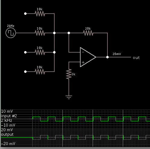
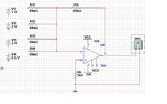
Could somebody help me with this one, i don't understand it. I have tried to build the circuit in multisim 11 but i'm not getting anywhere.
so if someone could take a look at the attached zip file and perhaps adjust it so at least the first part of the question works and explain what needed to be done.
I have built well i think most of the circuit but not finished as i got stuck
a – Build and test a summing amplifier with four input voltages V1, V2 , V3 & V4 using multisim . The amplifier should have a voltage gain of 1 , 2, 3 & 0.5 for V1, V2,V3 & V4 inputs
1. Set V1, V2, V3 & V4 to the following voltage levels 1, 2, 0.5 & 3. Monitor Vout with the Multimeter and verify that the voltage gain levels are set correctly.
2. Set V1 to 1KHZ at 10mVPP, V2 to 2KHZ at 20mVPP , V3 to 15 mVPP and V4 to 2V D.C. Monitor Vout with the scope and verify that the gain levels are set correctly. Explain your findings.
3. Modify your summing amplifier to convert the binary number 1101 to an equivalent analogue voltage.
Attachments
Last edited: