Continue to Site

Welcome to EDAboard.com

Welcome to our site! EDAboard.com is an international Electronics Discussion Forum focused on EDA software, circuits, schematics, books, theory, papers, asic, pld, 8051, DSP, Network, RF, Analog Design, PCB, Service Manuals... and a whole lot more! To participate you need to register. Registration is free. Click here to register now.

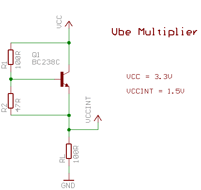
'Rubber diode' / Vbe multiplier

Status
Not open for further replies.

boylesg

Advanced Member level 4
Joined
Jul 15, 2012
Messages
1,023
Helped
5
Reputation
10
Reaction score
6
Trophy points
1,318
Location
Epping, Victoria, Australia
Activity points
11,697
I can find plenty of websites that explain the theory of these things but not one that explains them in a practical situation with a worked example.

I mean would you use a 1M pot or a 1k pot?

I see they are meant to be connected to a constant current source as well as the input audio signal. But how much current? 100mA, 10mA, 1mA or 1uA?

If any one can point me in the direction of a website that covers all practicalities as well as the theory I would be very appreciative.
 

I mean would you use a 1M pot or a 1k pot?
To make the circuit act as a programmable diode, you'll want Ipot << Ic and Ib << Ipot.

But how much current? 100mA, 10mA, 1mA or 1uA?
Suitable driver current seems to be related to base current of output transistors at full output power. It must be obviously larger, large enough not to cause additional distortion, but not larger than acceptable power dissipation and current consumption allows.

I doubt that you'll find web sites that comfortably provide every detail answer. My personal method to find the answer is think and calculate.

Additionally, electronic circuit simulation gives you the chance to experience the effect of every circuit element without assembling a real amplifier.
 

This webpage has some formulae.

**broken link removed**

Yeah I have been looking at this page but there are no values given here, just the theory.

I am still no closer to knowing with confidence how it actually implement one, short of doing trial and error with every combination of pot value and constant current value.
 

short of doing trial and error with every combination of pot value and constant current value.
Thinking would help, there's a hierarchy of both parameters. You'll decide first about driver current and then about Vbe circuit dimensioning.
 

Thinking would help, there's a hierarchy of both parameters. You'll decide first about driver current and then about Vbe circuit dimensioning.

I am a novice here mate. I really need a worked example to get my bearings so to speak.

I have since found this web site containing a specific example: https://www.jopdesign.com/cyclone/powerup.jsp.

I found another one where they used a 20k pot.

Quite wide variation here but perhaps I will stick with the larger resistance values so as to not waste too much current.

Two things of note on this website is that there is a load resistor in series with the rubber diode - I presume that is their version of a constant current source. I am assuming that you would want this constant current to be significantly smaller that the signal current level so as not too introduce to much DC interferance and/or so as not to waste power.

At Vcc = 12V, perhaps a 10k - 50k pot and a 10 - 100k load resistor?
tz.gif


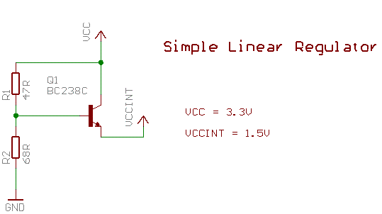
The other thing that I note on this web site is that they specify has a more efficient alternative to a Vbe multiplier - a linear regulator:

simpreg.gif


I have found plenty of examples of multiple transistor voltage regulators, so I suppose I could use any of them if I wished and could fit them on the board.

- - - Updated - - -

Finally! This web site has very practical info about rubber diodes: http://www.ece.drexel.edu/courses/ECE-E352/ClassABAmp.pdf

choose unique values? To get a better feel for the range of appropriate values,
look at the ac resistance of the VBE multiplier:
R2
(
R2
)
0.025V
r =- + 1+ - re' where re = ~ R1 le
This can be derived from the ac equivalent circuit of the VBEmultiplier.To produce a
nearly pure dc voltage drop of a given value you would want R2 small, B large and Ic
large.
Example 2
Calculate the ac resistance of the VBE multiplier in the previous
example.
lE = 1-1'= 2.5mA_ tOO.k7QV = t8mA
r = O.025V = 13.9Q
e t8mA
r = 3.3kQ +
(
1+ 3.3
)
13.9 = 33.0Q + 59.8Q = 92.8Q
100 to
Ifthis value of r is too high you could lower R2 (and R1), raise I, or
add a capacitor between nodes 2 and 3 with an impedance much
less than r at the frequencies of interest.
 
Last edited:

Status
Not open for further replies.

Part and Inventory Search

Welcome to EDABoard.com

Sponsor

Back
Top