Continue to Site

Welcome to EDAboard.com

Welcome to our site! EDAboard.com is an international Electronics Discussion Forum focused on EDA software, circuits, schematics, books, theory, papers, asic, pld, 8051, DSP, Network, RF, Analog Design, PCB, Service Manuals... and a whole lot more! To participate you need to register. Registration is free. Click here to register now.

choosing from inverting and non-inverting opamps

Status
Not open for further replies.

elecfan

Member level 1
Joined
Nov 8, 2012
Messages
34
Helped
0
Reputation
0
Reaction score
0
Trophy points
1,286
Location
Earth
Activity points
1,571
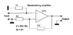
in addition to the polarity of the output, what other differences the two amplifiers have?

In choosing an amplifier from the two, should I consider other issues

Thanks
 

There are no 'inverting and non-inverting' opamps - there are only opamps, which you do what you want with.

You decide in your circuit whether to make the opamp inverting or not, by how you connect it.
 

yes, you are right. but still my question remains.
is inverting config different with non-inverting, in other aspects?
 

yes, you are right. but still my question remains.
is inverting config different with non-inverting, in other aspects?

I know what you mean - you speak about inverting/non-inv. amplifiers realized with opamps.

Yes, the main difference is the input resistance.
The inverting configuration has an input resistance, which practically is identical to the "first" (external) resistor R1 (because of the virtual ground concept).
The non-inv. configuration has a very large input resistance (opamp internal input resistance multiplied with the loop gain).
 

and do they effect on the signal characteristics differently, or they are all the same? (except polarity and gain formula)
do they have different applications?
I read somewhere that non-inverting is closer to ideal opamp.
 

and do they effect on the signal characteristics differently, or they are all the same? (except polarity and gain formula)
do they have different applications?
I read somewhere that non-inverting is closer to ideal opamp.

As far as the input resistance is concerned - yes, the non-inv. configuration is closer to the ideal opamp.
Beyond this property I see no further unwanted influence on signal characteristics.
(If the signal source has a very small internal resistance - ideally zero ohms - even the amplifiers input resistance does not matter).
 

Hello elecfan,

here are some explanation:

The inverting OPamp

inverted the signal.

It's a current input.

This input is virtual grounded insides, so that the input resistor is only dependend from the connected resistor R1 in the attached circuit.
Inv. OP.JPG
The amplification will be adjust by the ratio of R2 / R1 for R2 ≧ R1 and R1 ≠ 0 and R2 ≠ 0. The min. ampliflication Is "1".

You can use it as summing point to a lot of inputs
Summ. OP.JPG
The amplification will be adjust by the ratio of R2 / R1. R1 of each Input can be different from each other. So you can adjust the amplification of each input.

The non-inverting OPamp

The output follows the input

The input resistance is very high and not dependend from serial resistors. The input resistance is only dependent from the parallel resistor R1 if exist.
V=1+(R3 / R2). R2 and R3 can be "0". If R2 and R3 are exist, the min. amplification will be > "1".
Noninv.OP.JPG
A special case of this circuit is show here:
Spec. Noninv. OP.JPG
In this case the amplification is "1".

Regards

Rainer
 

Attachments

  • Noninv.OP.JPG
    Noninv.OP.JPG
    30.9 KB · Views: 88
I think some minor corrections to Rainer`s posting are in order

It's a current input.

No, I don`t think so. It is a voltage input (otherwise the gain formula Vout/Vin=-R2/R1 makes no sense).

This input is virtual grounded insides, so that the input resistor is only dependend from the connected resistor R1 in the attached circuit.

The "virtual ground" exists (is created automatically) by the feedback action in conjunction with the vry high open-loop gain of the opamp.

The amplification will be adjust by the ratio of R2 / R1 for R2 ≧ R1 and R1 ≠ 0 and R2 ≠ 0. The min. ampliflication Is "1".

If you want there is, of course, no restriction to select the ratio R2/R1 lower than unity. Thus, the min. amplification can be below "1".
 
Status
Not open for further replies.

Similar threads

Part and Inventory Search

Welcome to EDABoard.com

Sponsor

Back
Top