Continue to Site

Welcome to EDAboard.com

Welcome to our site! EDAboard.com is an international Electronics Discussion Forum focused on EDA software, circuits, schematics, books, theory, papers, asic, pld, 8051, DSP, Network, RF, Analog Design, PCB, Service Manuals... and a whole lot more! To participate you need to register. Registration is free. Click here to register now.

interface c3088 camera with xilinx spartan-3

Status
Not open for further replies.

Robin Khosla

Member level 4
Joined
Aug 2, 2012
Messages
76
Helped
7
Reputation
14
Reaction score
6
Trophy points
1,298
Activity points
1,861
I want to interface camera c3088 with spartan-3

c3088 has Y(8-bit) output
i want to get this output on 8 LED's of FPGA
can u correct my following code
i am unable to do get the output on leds and confused in the i2c interface


library IEEE;
use IEEE.STD_LOGIC_1164.ALL;
use IEEE.STD_LOGIC_UNSIGNED.ALL;
-------------------------------------------------
entity cam1 is
Port ( rst : in STD_LOGIC;
clk : in STD_LOGIC;
rw : in STD_LOGIC;
crst: out STD_LOGIC;
scl,sda:inout std_logic;
cam_pclk : in STD_LOGIC;
cam_href : in STD_LOGIC;
cam_vsync : in STD_LOGIC;
agnd1 : out STD_LOGIC;
agnd2 : out STD_LOGIC;
agnd3 : out STD_LOGIC;
gnd1 : out STD_LOGIC;
vcc1 : out STD_LOGIC;
vcc2 : out STD_LOGIC;
cam_y : in STD_LOGIC_VECTOR (7 downto 0);
cam_o : out STD_LOGIC_VECTOR (7 downto 0));
end cam1;
-------------------------------------------------
architecture cam2 of cam1 is
signal crst1:std_logic;
signal i:integer:=13;
signal count: std_logic_vector(25 downto 0);
signal data: std_logic_vector(12 downto 0):="0000110000011"; -- c1 for read
begin
process (rst,clk,rw,cam_vsync,cam_href,cam_pclk)
begin
if (rst='1') then
cam_o <= (others => '0');
elsif (clk'event and clk='1') then
count<= count+1;
if (cam_vsync='0' and rw='0') then
if (cam_href='1' and cam_pclk='0') then
cam_o <= cam_y;
end if;
end if;
agnd1<='0';
agnd2<='0';
agnd3<='0';
gnd1<='0';
vcc1<='1';
vcc2<='1';
crst1<='1';
crst1<= not crst1 after 100 us;
crst<= crst1;
end if;
end process;
scl<= count(25);
process(scl,sda)
begin
if (scl'event and scl='1') then
if (i<=13) then
sda <= data(i);
i <= i - 1;
end if;
end if;
end process;
end cam2;


the datasheet of c3088 and ov6620 are also attached
 

Attachments

  • c3088.pdf
    37.4 KB · Views: 52
  • ov6620.pdf
    330.9 KB · Views: 60

You shouldnt come here with so many questions that follow the same general pattern "I dont understand - someone do my work for me". You should try to get things working and then construct questions that a specific.

Anyway, before we move on to why it doesnt work, lets fix some VHDL/digital logic knowledge gaps you appear to have:

1.
process (rst,clk,rw,cam_vsync,cam_href,cam_pclk)

You dont need all these signals in the sensitivity list, you only need clock and reset as its a sync process with an async reset,

2. You shouldnt place signal assignments outside of the clock branch. If you expect them to be async logic, they should be placed outside the process.

3.
crst1<= not crst1 after 100 us;

This will not work on real hardware. "after" statements are ONLY for simulation purposes, so it will be removed when synthesised, and in this case will create a logic loop, and will probably oscilate at very high frequency. You need to put in a counter and comparitor that works out when the 100 us is up, based on the counter clock.

4. the i signal is a 32 bit signal, completly unessesary. It wil also be always less than 13, because you initialise it to 13 and never reset it to anything, so just goes negative.

I highly suggest you read up on VHDL and digital logic, and then come back with more specific questions.
 

thanks

But my vhdl code is synthesizable, just i wanted to know about the address of the registers of c3088 where to send 0C1
because its nearly 3weeks and i am not able to sort this problem of registers for the sccb protocol??.....
earlier i asked specific questions regarding these but i am not getting any relevant answer thats why this time i gave more detail regarding the project with code..

Errors which you are highlighting are of not much concern because no errors are displayed by the tool.
1. what does it effect if we give all inputs in the sensitivity list (i studied that we have to give all inputs in sensitivity list)
2. if i place signal assignments outside the process they give error in synthesis in this code.
3. I agree with this point.
4. 'i' signal is not unnecessary, it is used for clock divider just for testing purpose that's why i have taken it as integer. if it is not used than how will we see the output on FPGA.
 

1. what does it effect if we give all inputs in the sensitivity list (i studied that we have to give all inputs in sensitivity list)

Not alot with synthesis because the list are ignored, but it can slow down simulation. You have also technically missed out crst1 from the list, so it will not simulate correctly.

2. if i place signal assignments outside the process they give error in synthesis in this code.

Then there is an error you need to fix. Having signals like this inside a process can lead to simulation/synthesis behaviour missmatches because of signals not in the sensitivity lists.

3. I agree with this point.

Good

4. 'i' signal is not unnecessary, it is used for clock divider just for testing purpose that's why i have taken it as integer. if it is not used than how will we see the output on FPGA.

but in your code it is never reset, and so the comparitor is redundant, because it never goes above 13. in the real implementation, when it finally wrps aroung to 2^31 it will stop counting and sda will not accept values from data
 

thanks

do you find any document regarding the registers of c3088
 

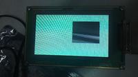
i programmed the registers and viewed the pixels on led's but not able to get the image on lcd, only snow is seen on lcd, image is not formed

i am not able to figure out where the problem has anyone faced the same problem
 
Last edited:

have you got a controller for the type of screen it is (vga/DVI)? it will need various timing signals along with the data.
 

i have tested the lcd it is working fine as i read the data from rom and displayed on it . all the timing signal are also right in lcd..

the problem is in camera c3088. i thing timing problem is causing this because camera pixel clock is 17.73mhz and tft screen is 10mhz


however i am not able to achieve 17.73mhz(56ns) but infact 16.66mhz (60ns)
 

if the clock rates are different then the formats will be different. You will need a standards converter.
 

i have interfaced c3088 camera and vmodtft with virtex-5
i am getting pixels out but proper image is no formed (see attachment)
the pixels from the camera are shown in 176 * 144 window on the screen


i am not able to figure out the problem that why image is not displayed???
 

Status
Not open for further replies.

Part and Inventory Search

Welcome to EDABoard.com

Sponsor

Back
Top