Continue to Site

Welcome to EDAboard.com

Welcome to our site! EDAboard.com is an international Electronics Discussion Forum focused on EDA software, circuits, schematics, books, theory, papers, asic, pld, 8051, DSP, Network, RF, Analog Design, PCB, Service Manuals... and a whole lot more! To participate you need to register. Registration is free. Click here to register now.

Charging a LiPo battery from a 3V solar cell

Status
Not open for further replies.

Artlav

Full Member level 2
Joined
Nov 26, 2010
Messages
144
Helped
2
Reputation
4
Reaction score
2
Trophy points
1,298
Activity points
2,723
Hello.

I want to be able to charge a LiPo battery from a solar cell.
The cell gives out 3.2V and 80mA.
How is this solved normally?

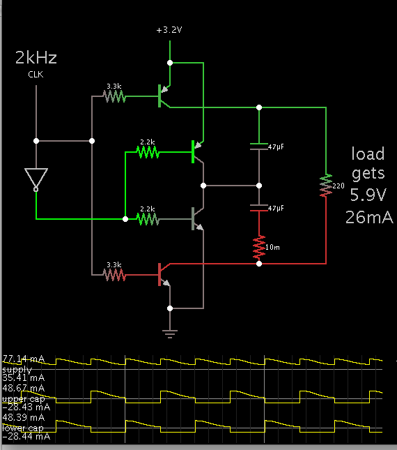
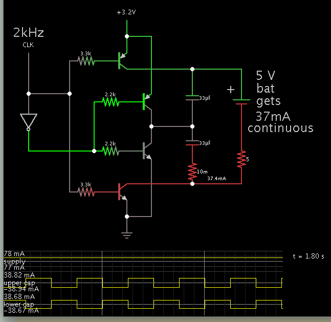
What i can think of is to use something like MAX660 charge pump chip to double the voltage, then feed that into some sort of regular lipo charger chip, like MAX1555.
Would that work?
The cell can give up to 4.2V open circuit in full sun, that means 8.4V at the 7V max rated MAX1555 - is that a problem, if yes is it easily solvable?
Are there better chips (not too rare or expensive) that would do the whole, or some parts better?
 

There are a bunch of boost converter chips on digikey that feature adjustable voltage output via voltage divider.

- - - Updated - - -

These usually require and inductor and capacitor, in addition to a few resistors to function properly:
http://www.digikey.com/scripts/dksearch/dksus.dll
If you use a potentiometer instead of fixed resistors, you can also make an high efficiency adjustable voltage power supply.
 

MAX660+MAX1555+LP2950 gives an efficiency of about 65%-70%, at 55mA@3V input the battery is fed with 26mA@4V of charging current.
Any way to do better?

There are a bunch of boost converter chips on digikey that feature adjustable voltage output via voltage divider.
These usually require and inductor and capacitor, in addition to a few resistors to function properly:
https://www.digikey.com/scripts/dksearch/dksus.dll
If you use a potentiometer instead of fixed resistors, you can also make an high efficiency adjustable voltage power supply.
That's a link to DigiKey search, without anything specific. Was that your intention?

Boost converter chips that need inductors are a bad idea, since i'm limited in the board thickness.
 

Sorry about the link. You can use
https://www.digikey.com/product-detail/en/TPS61220DCKT/296-24170-1-ND/2003238
Because of it's fast 2MHZ switching frequency, you can use much smaller capacitors and inductors than you normally would.
This inductor is only 1.25mm high. That's plenty small for most applications. It's also rated at 3.3uh, which is 50% more than the 2.2uh rating required by the chip.
https://www.digikey.com/product-detail/en/MLZ2012A3R3W/445-6394-2-ND/2465152
You're looking at up to 95% efficiency in this configuration, and that's pretty good.
Sorry about responding so late, I didn't get any notifications by email and I'm pretty busy with my own projects, but I wish you luck on yours!
 

Connect more solar cells in serie to get higher voltage.

Voltage boosters is bad idea, you will lose lots of current, and make all unusable.

Test cells on average ammount of sun, what is voltage and current production.

Check newer solar guarden lamps, they start to implement stronger solar cells inside. I make solar cell from thise.
 

Sorry about the link. You can use TPS61220DCKT
Nice.
Some TPS61220 arrived today, and the result is about nil, unfortunately.

It works ok from a 1.5V battery or similar. but not from the panel even at medium light.
If i read the datasheet right, it needs 200ma to start or something.

With a solar panel, the panel voltage drops to 0.5V, as it sucks out all the dozens of ma of current it can, without giving any output.
With a 1.5V battery it does not **** any measurable current, and gives out 5V.
Load, or no load.

Am i doing something wrong, or is it a wrong chip?

- - - Updated - - -

Another thing i tried is the MCP1252 charge pump, which converts 2.7..5.5V directly into 5V.
While this works 4 to 10 times better than an LDO going from 3.8V to 3.3V, it still works 3 times worse than a doubler with an LDO from 3V to 6V and down to 5V.

Counter-intuitively, MAX660+LP2950 pair gives the best result so far.
 

As one good solution you can get this cheap devices (in my country around 10eur). Device have Li-Ion battery inside around 4-5Ah and solar cell, 5V USB output and lots of device adapters.

**broken link removed**

**broken link removed**

Sorry for this color I'm normal.
 

I have been playing with a simulation of a voltage doubler based around a stack of 2 capacitors.

It appears to be very efficient. It might work for your situation.


First one pair of transistors charges one capacitor. Then that pair shuts off and the other pair turns on to charge the other capacitor.

Each capacitor is alternately charged to the incoming supply voltage. The load gets twice the supply voltage.

The clock can be an astable multivibrator driven from the solar cell.
It can be the common type made from 2 transistors, or the type made from a cmos 4069 inverter IC. Etc.
 

As one good solution you can get this cheap devices (in my country around 10eur). Device have Li-Ion battery inside around 4-5Ah and solar cell, 5V USB output and lots of device adapters.
This charger is larger than the device i'm making, it's just not an option.
As for putting one apart to find a nice schematic - these things often contain weird Chinese parts that i won't find anyway.

I have been playing with a simulation of a voltage doubler based around a stack of 2 capacitors.

It appears to be very efficient. It might work for your situation.
It appears to have about 70-80% efficiency, while doing exactly what MAX660 chip is doing already, at 92-96% efficiency and in much smaller space.
So, it appears to be mostly useless for me.

I guess at this point i'm looking for either a charge pump booster like MAX660, only with a 6V voltage limiting.
Or, a lipo charger chip than can accept up to 9V, so i could connect MAX660 to it.

Lastly, some harmless way of connecting 6V rated MAX1555 to could-give-8.6V-MAX660.
The voltage should sag under load, so the protection is only needed when the thing is in full sun with battery fully charged.
 

I attached a 5V battery to my stacked-capacitor voltage doubler. It gets 37 mA continuous charge (in the simulation).


Disregard the token resistors below the cap and the battery.

The draw on the power source remains 77 mA continuously as before. Its efficiency is about 75%, similar to what you quoted.

Remember the PV panel has its own internal resistance. If its best power point is 3.2V at 80 mA, then that's like having a resistance of 40 ohms inline.

So don't be surprised if a switched-coil converter is unable to give you more than 30 mA average charging current into a 5V battery.
 

Status
Not open for further replies.

Part and Inventory Search

Welcome to EDABoard.com

Sponsor

Back
Top