Continue to Site

Welcome to EDAboard.com

Welcome to our site! EDAboard.com is an international Electronics Discussion Forum focused on EDA software, circuits, schematics, books, theory, papers, asic, pld, 8051, DSP, Network, RF, Analog Design, PCB, Service Manuals... and a whole lot more! To participate you need to register. Registration is free. Click here to register now.

А - V meter on ATmega8.

Status
Not open for further replies.

DeepOne

Advanced Member level 2
Joined
Feb 26, 2011
Messages
632
Helped
99
Reputation
200
Reaction score
100
Trophy points
28
Location
45N39E, Russia
Activity points
0
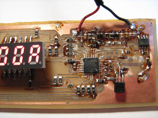
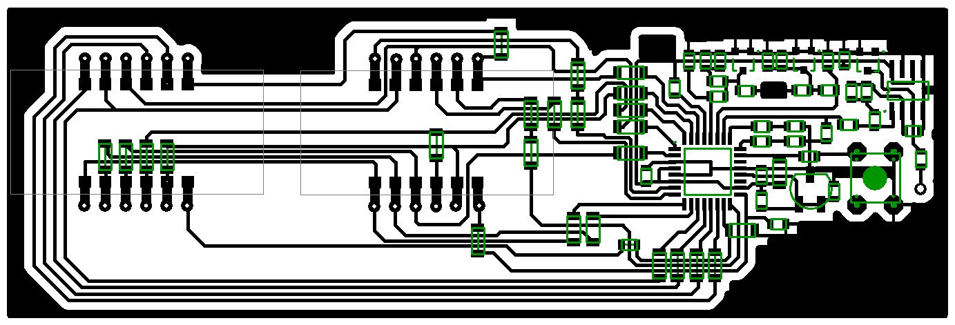
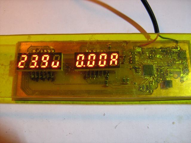
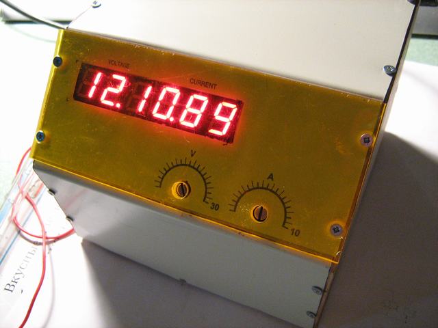
Based on project from http://radio.aliot.com.ua/?p=499 page.
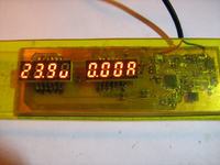
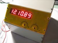
Design stands out with improved accuracy of voltage measurement and automatic recognition of the type of 7-segment LED display (this function works only with 4- digits displays).
Function of protection from excess of the current is possible not to use if this is not required.

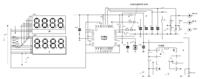
.hex is possible take from this place:
http://www.aliot.com.ua/files/avmeter2/avmeter2_eep.hex
 

Hi, Naseerak.
There two versions of this firmware. First, "avmeter2.hex" with separate file "avmeter2.eep". But second version, "avmeter2_eep.hex", prescribes parameters of eeprom itself under first start.
 

Hi, Deepone.
The link you provided is for DIP version of the meter.The page is not in english. I am not asking to provide translation.I can not understand the input pins in the schematics.Google translation does not help very well.
So could you please explain it a little,like calibration procedure etc.And where the pins need to be connected.
I have all the parts for DIP version.I am making a dual bench power supply for my self.The addition of such meter will be nice and cost effective.
I shall me much thankful for any help.
 

According to the schematic Bu1 is the power supply, Bu2 is the voltage input, Bu4 the current input, Bu5 the ground.

I'm not sure about Bu3 , probably an indication output.
 

Hi, all.
Certainly, Alexan_e is right -
" Bu1 is the power supply, Bu2 is the voltage input, Bu4 the current input, Bu5 the ground."
And "Bu3" is output for overcurrent protection, its threshold tunes by the R13 (for entering current protection turning mode it is necessary to provide short striking on button S1 . For returning in normal mode it is necessary one more short striking on this button. For unset of protection is required long striking on button. Possible use this funtionality simply for indication of the excess of the current, connected here to buzzer.
Since this voltmeter is working in two range - 0 - 10V and 10 - 99V so for adjusting first we employ 5V on voltage input (Bu2) and elaborate value of R21 -R22 divisor, whereupon we adjust R23 - R24 divisor at voltage above 15V.
Current meter tunes is concluded in determination of the value of amplification R25 and R27 shunt resistance.
 

Hi,
So the protection part of the circuit can be left unconnected.?
Still confused with the following.
On the design and configuration. Structurally everything is on one board. Connectors for in one row and have a fairly large contact. The device requires a separate power supply within 7 ... 15V. The thickness and length of the wire is critical to connect a ground wire and wire «- Rn» - these two wires should be as thick and short. Wire «-Rn» is connected directly to the negative output terminal. Shunt resistance, as such, can not measure everything - Chinese multimeter is not able to measure up, so setting the channel ammeter comes to setting the gain op amp IC4. Shunt resistance ratings for the scheme should reach 3.62 m (illi) ohms. Really - will pick up the resistor R25. As the shunt I used half of the spiral coil of a fireplace heater thickness of about 1 mm and a diameter of 5 mm.
Its result of Google translation.
 

So the protection part of the circuit can be left unconnected.?
Yes, it is optional. In this case possible not to install S1, C3, R12, R13, R14, R15, LED3 and pin 25 (PC2) of mcu must be shorted to ground.

In authors variant of scheme is chose big gain for OP AMP, herewith on the out of amplifier can appear small voltage without any current over shunt resistor. In such event possible to set zero on display by the short and than long pressing button S1.
When adjusting is useful to bear in mind that maximum value on led display corresponds to 2,5V on mcu input pins.
 
Last edited:

Thank you very much,DeepOne.
Understood.I will come back with results as soon as i finish building it.The MCP devices are not available to me so i am going to use MAX495 although priced very high yet its rail to rail op-amp and low voltage.
 

LM358 is also suitable because it "allows direct sensing near GND and Vout also goes to GND".
Possible use any 5V charger from old cell phone for MCU feeding. Beside me the cost of such device forms around 0,6 USD.
 
Last edited:

Good to hear that,DeepOne.
The price in my country for Max495 is like 3.95 USD.The LM358 for 0.6 USD.A cell phone charger new genuine Nokia for 1 USD.Third party charger 0.5 USD.Cheep things yet good for every one(not to mention my latest black berry charger.genuine brand new not available.Little used almost new and genuine for 15 USD, Damn....)
Obviously i will use LM358 for prototype.
 

Before using such source as cellphone charger it is necessary to open it and make sure in reliability of insulation and presence of sufficient value of output voltage.
 
Last edited:

Right.
For my side most of them have TL431 and opto isolator based secondary regulation and protection.SO the output is adjustable by editing the divider resistors.
 

Hi,again.
Got some time last night to work at the meter.Made it on bread board.Loaded unmodified initial version of firmware.Got it working.
with original combination of R21,R22 and R23,R24 the voltage reading were too off the scale.So as author said,tweaked a little with these.I used Bourns precision trimmers 100turns types at R22,R24 to adjust it. Is it the right way to do while did not made any change to R21,R23.
For now voltage is measurement section is working,seems right.Compared it to my Multimeter which is so for known to me to be accurate.The measurements are almost identical.
Did not tried to calibrate the current measurement section, still don't know how to select the R27's value.A little help is needed.
Thank you.
 

Hi, Liteon.
There is sense to choose R27 value as, on the one hand for not lose too big power and on the other hand that voltage must be more for increasing accuracy of the measurement. I think 0,01 - 0,03 Ohms is suitable. In this case the fall of voltage is will be 0,1 - 0,3V at 10A current through R27. And OP AMP gain accordingly must be 2,5/0,1 = 25 or 2,5/0,3 = 8,3.
 

Hi,deepone.
Tried the current measurement section.Failed.Remember that i left the part of over-current protection.As you mentioned in your earlier post.The situation is so that the meter shows a fixed 3.32A reading with or without any load.Tried to change the op-amp no success.Put An ICL7660 to provide the op-amp with dual supply,still nothing.The voltage at pin 1 of LM358 remains constant at 4.8v,Won't change under load or no load.Disconnecting the pin 26 of Mcu makes it to show rapidly changing values at display for current.
Checked the placement of parts on bread board many times but found no error.
What could be possible cause of such behavior of the op-amp.
Thank you.
 

try to change voltage on pin 26 (disconnected from op amp) from 0 to 2,5V - meter shows must change from 0 before 9,9A. If so that mcu works is correctly.

The voltage at pin 1 of LM358 remains constant at 4.8v
It is necessary to measure voltage also on LM pins 2 and 3 and value of R25 & R26.
What could be possible cause of such behavior of the op-amp.
not so much possibilities - or feedback, or voltage on entry pins.
 
Last edited:

Did it.But up to 2.5v at pin 26 gives 0.00A. At 3.1V reads 0.16A.
 

For diagnosticsquite well measure voltage on "aref" mcu pin (21). Lefting the part of over-current protection, as i test on my scheme at this moment, does nothing. And possible not to connect pin25 to ground.

Loaded unmodified initial version of firmware.
I check this device only in work with this version of firmware:
https://www.aliot.com.ua/files/avmeter2/avmeter2_eep.hex
 

the voltage measurements are as follows.(with the respect to GND)
Voltage applied 12.5v a load of 25W,12v light bulb.
Pin1= 4.95v
Pin2=0.10v
Pin3= 0.08v

disconnected input and removed the load.
Pin4 same 4.95 volts.
remade the op-amp circuit part at different place on bread board,Still same.
R25 68K, R27 0.01 R. R26 1K,R28 10K. VD3 5.6v zener.

- - - Updated - - -

Reloaded your version of hex file.Now the meter reads -.--A.
Pin 21 voltage is 4.5V.
Need clarification with the button functions too.should i press it for long time to reset the current measuring section.
 

Status
Not open for further replies.

Similar threads

Part and Inventory Search

Welcome to EDABoard.com

Sponsor

Back
Top