Continue to Site

Welcome to EDAboard.com

Welcome to our site! EDAboard.com is an international Electronics Discussion Forum focused on EDA software, circuits, schematics, books, theory, papers, asic, pld, 8051, DSP, Network, RF, Analog Design, PCB, Service Manuals... and a whole lot more! To participate you need to register. Registration is free. Click here to register now.

the Colpitts oscillator

Status
Not open for further replies.

lephuduc.90

Newbie level 5
Joined
Sep 29, 2012
Messages
9
Helped
0
Reputation
0
Reaction score
0
Trophy points
1,281
Activity points
1,348
collpitts.png
Can u expain me how the transistor work? the function of Cf and C1? the phase-shift of the circuit? Thanks
 

The colpitts oscillator consists of a tuned circuit made up of inductor L1 and capacitor CT (sometimes called the tuning capacitor) and a transistor in common-base mode. At the frequency of operation for the circuit, the capacitor C1 on the base of the transistor prevents the base moving (rising and falling) and this puts it in the common-base configuration.
Resistor Rb is the base bias resistor. It is designed to turn the transistor on at the beginning of the cycle.
Re is the emitter resistor and keeps the emitter from the 0v rail so the emitter can be injected via capacitor Cf (the feedback capacitor) to keep the oscillator operating.

Please read the Colpitts oscillator section of this webpage:
http://talkingelectronics.com/pay/BEC/Page23.html
 
This Colpitts is difficult to keep going.

It is in common base operation. The transistor is biased to a constant stable volt level. C1 is a smoothing capacitor.

The transistor alternates between conducting a little, and conducting a little more.

The capacitor Cf taps into the cycles of the LC tank loop, and applies a bit of that energy to the emitter leg of the transistor (a characteristic of common base operation).

Let us suppose Cf is momentarily sending a positive current down to the emitter. This raises the volt level at the emitter leg. In doing so it effectively reduces the bias voltage. The transistor conducts less through C-E. This reduces current through the tank.

Next, suppose Cf is pulling current from the emitter leg. This effectively raises bias voltage. The transistor conducts more. This increases current through the tank.

The action alternates. It is sufficient to provide the necessary nudge to sustain oscillations.
 
can u show me how each components be calculated?
 

I am using an animated interactive simulator at the falstad.com website.

The diagram shows what I constructed. I can observe the action in the wires. I can watch scope traces.


Click the link below to open the website, load my schematic, and run it on your computer.


You can adjust values if you wish. Right-click a component to bring up an edit window.
 
After sending my post I saw Not-a-moderators's post. I agree with what he stated.

Besides the fact that he has copied it from the referenced link I have the feeling that the role of the feedback capacitor Cf is not explained up to now.

It seems to be very easy to say "the tank circuit oscillates and Cf provides positive feedback."
However, a closer look reveals that this feedback path consists of Cf and the emitter resistor forming a high pass with a corresponding phase shift.
So - how do we get a loop gain with 0 deg phase shift?
Answer: The frequency of oscillation is not identical to the tank center frequency (with phase 0 deg) but displaced by a certain amount - causing a phase shift which can compensate the unavoidable phase shift in the feedback path.
That is the reason, the formula for the oscillation frequency contains both capacitors.
 
However, a closer look reveals that this feedback path consists of Cf and the emitter resistor forming a high pass with a corresponding phase shift.
So - how do we get a loop gain with 0 deg phase shift?
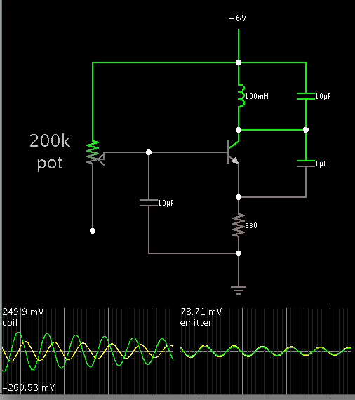
The colpitts oscillator circuit mostly shown in text books, also in this link https://en.wikipedia.org/wiki/Colpitts_oscillator uses a capcitive volateg divider instead of a high-pass feedback. Both circuits can work as an oscillator, but I prefer the classical circuit.
 
Besides the fact that he has copied it from the referenced link I have the feeling that the role of the feedback capacitor Cf is not explained up to now.

It seems to be very easy to say "the tank circuit oscillates and Cf provides positive feedback."
However, a closer look reveals that this feedback path consists of Cf and the emitter resistor forming a high pass with a corresponding phase shift.
So - how do we get a loop gain with 0 deg phase shift?
Answer: The frequency of oscillation is not identical to the tank center frequency (with phase 0 deg) but displaced by a certain amount - causing a phase shift which can compensate the unavoidable phase shift in the feedback path.
That is the reason, the formula for the oscillation frequency contains both capacitors.

I find you are correct. I see the coil interacts with both capacitors.

I tried putting a resistor instead of Cf. Then I watched the simulation. The resistor diverts current around the transistor. Oscillations fade.

Seeing this, it would lead me to think the purpose of using a capacitor here is to block DC current.

However you point out that the capacitor Cf provides a certain amount of phase shift. (The OP was aware that a phase shift might be in the equation. I was not aware of it. I believed the LC tank determined frequency.)

So now I am looking closer. The LC loop is not exactly in sync. The coil responds to both the capacitor Ct and the transistor, and the transistor responds to Cf.

Therefore both capacitors influence the coil action. The Talking-Electronics article does not touch on this.

In addition to LvW's clarification here, there have been previous threads here which touch on these points.

I located a similar Colpitts schematic from a previous thread. There is mention of a phase difference.

https://www.edaboard.com/threads/250013/

More threads about LC and Colpitts oscillators:

https://www.edaboard.com/threads/249228/

https://www.edaboard.com/threads/232066/
 
could you show me eqs to calculate (design) each components to make the circuit well-work?
 

My schematic in post 7 shows what values were suitable to sustain oscillations for many cycles, until they decayed. To get continual oscillations will require more work in the simulator, and even more work with real hardware.

If you want a certain frequency, we can make an approximate calculation if we were to look only at the LC tank. It is influenced by the usual formula: f = 1/ ( 2*Pi* SQRT(LC)).

It often works well when the coil value is 100 to 10,000 times the capacitor value.

LvW mentioned a formula (post #8) which includes both capacitors. It might be found by internet search. I don't remember seeing it at the Talking-electronics webpage.
 
A good rule of thumb is to design the bias to get about 20% of the supply voltage over the emitter resistor. I usually pick the emitter resistor around 150-470 ohm depending on what I want to connect the oscillator to eventually.
 

Status
Not open for further replies.

Similar threads

Part and Inventory Search

Welcome to EDABoard.com

Sponsor

Back
Top