Vermes
Advanced Member level 4
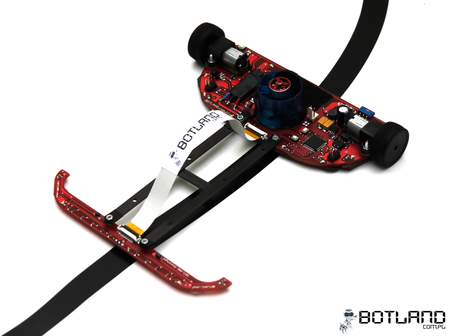
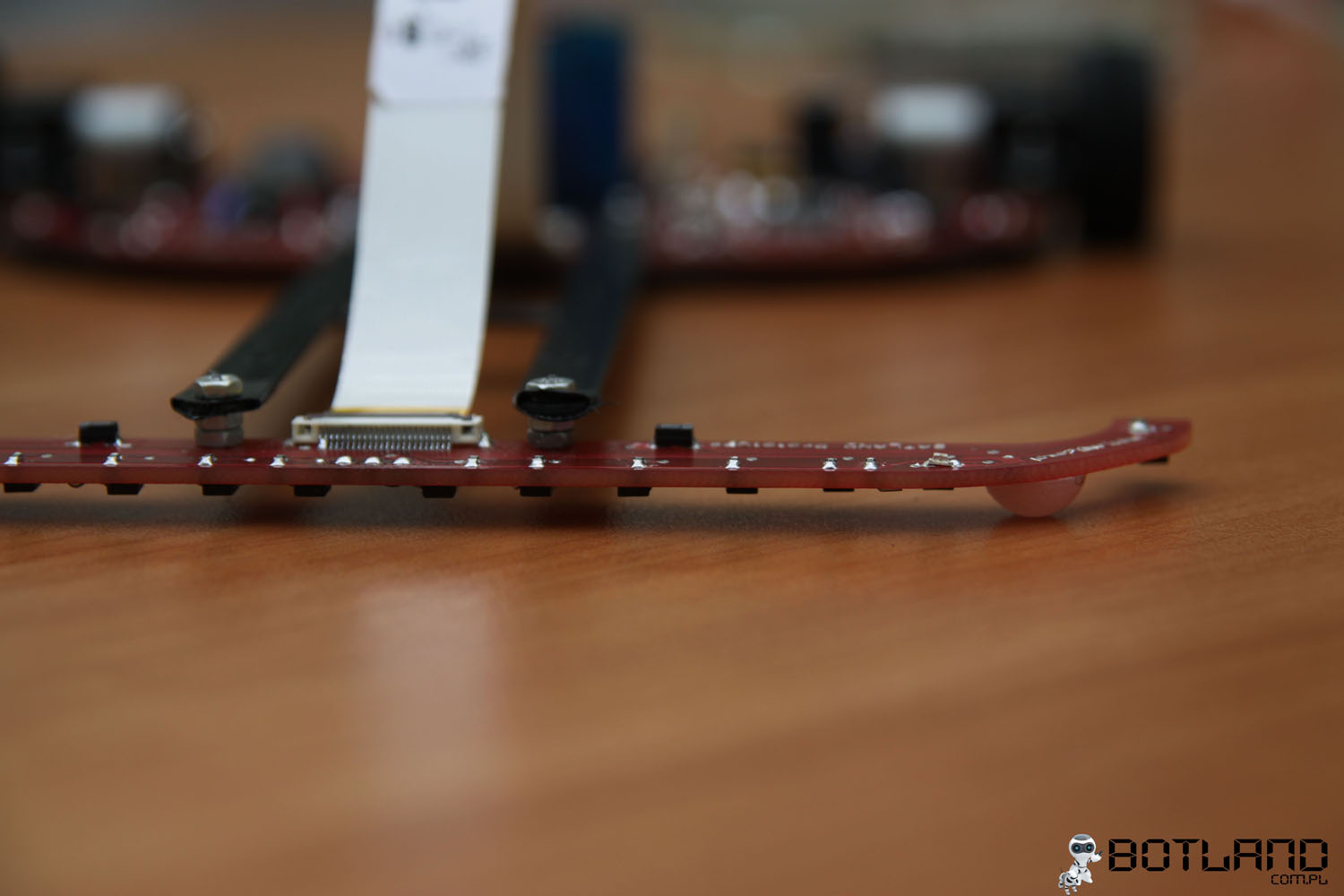
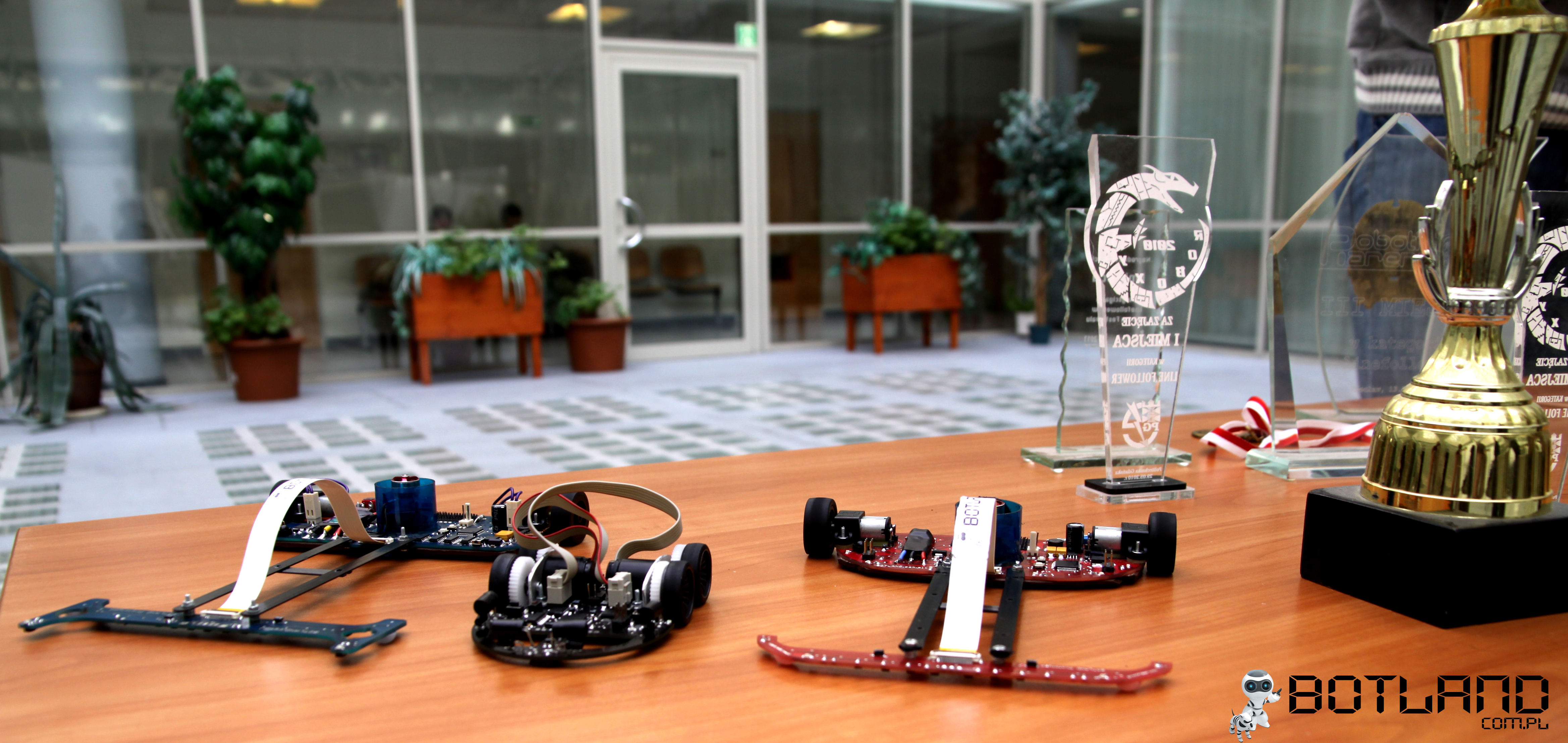
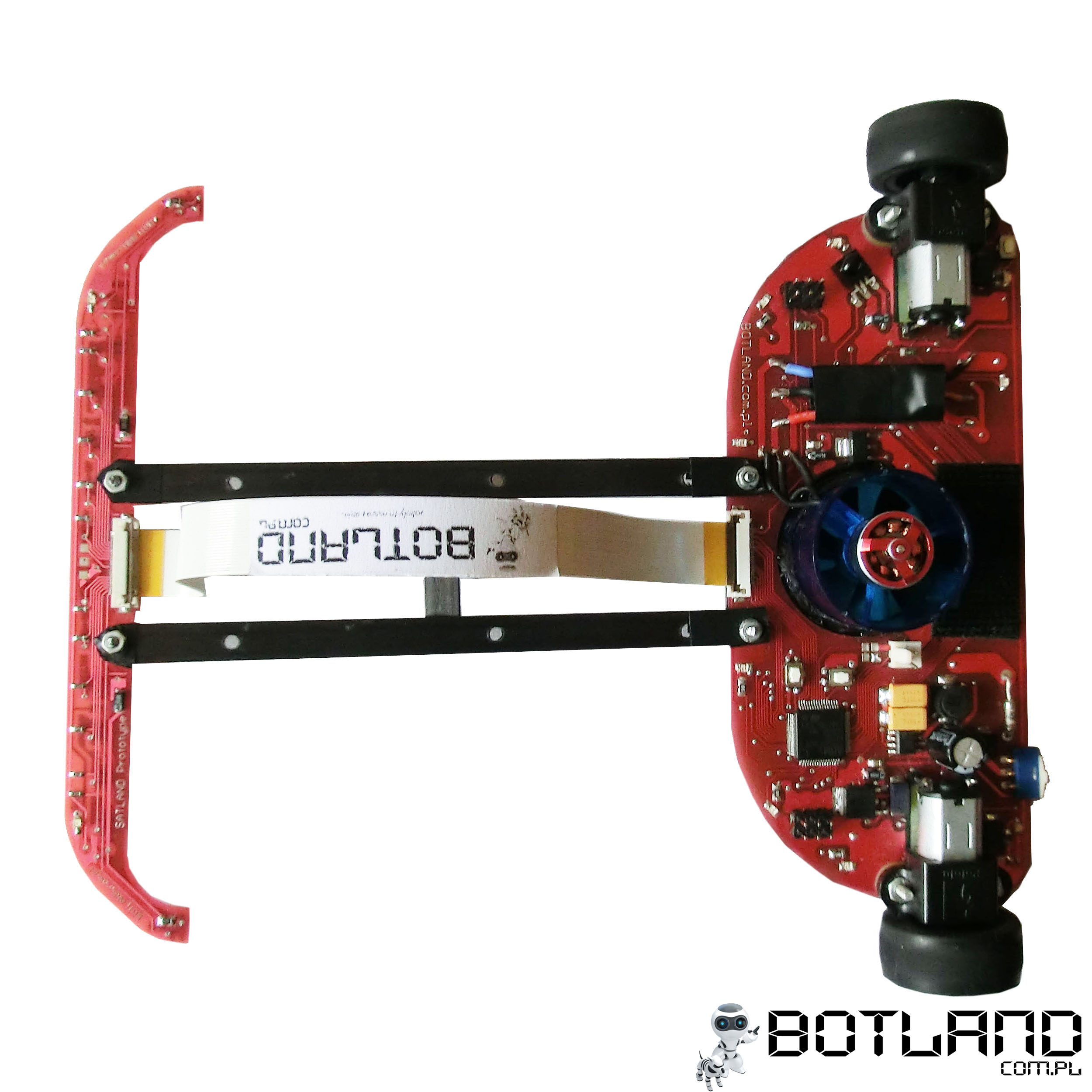
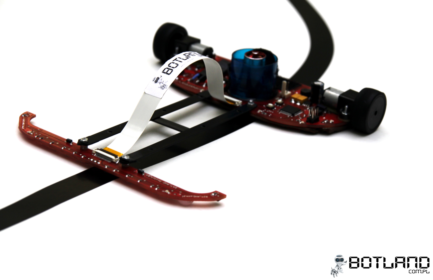
It is a design of line follower robot Impact. The vehicle consists of two modules: main board and board with sensors, connected together by light carbon strips. The device weighs 105g together with an accumulator.
Module with sensors:
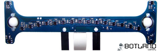
This element is the furthest from the center of rotation. The moment of inertia is large (mass multiplied by the square of the distance from the center of rotation). Because of that, mass of the board should be as small as possible to make it possible to pull away sensors. In the previous version, there were 19 sensors, 16 of which were arranged in an arc, 4 put forward to the front and to the rear. The board also consisted of comparators and a potentiometer to set the threshold value. The following picture presents the arrangement of sensors in the previous version of this device.
The final version uses only 14 sensors, arranged in greater distances from each other. That made it possible to remain unchanged the spread of the furthest sensors. Pulled forward sensors were removed, because there is no point to use sensors in such arrangement in the final version as at high speed the robot can not react effectively to the signal coming from them. Reducing the number of sensors allowed to use analog-digital converter built-in the microcontroller (16 multiplexed inputs), which in turn allowed to remove the comparators. The thickness of laminate used in comparison to the initial version (1,5mm) was also reduced to 0,8mm. Those actions resulted in two times reduction of the weight of the PCB from 8 to 4g. The module looked like in the picture below:
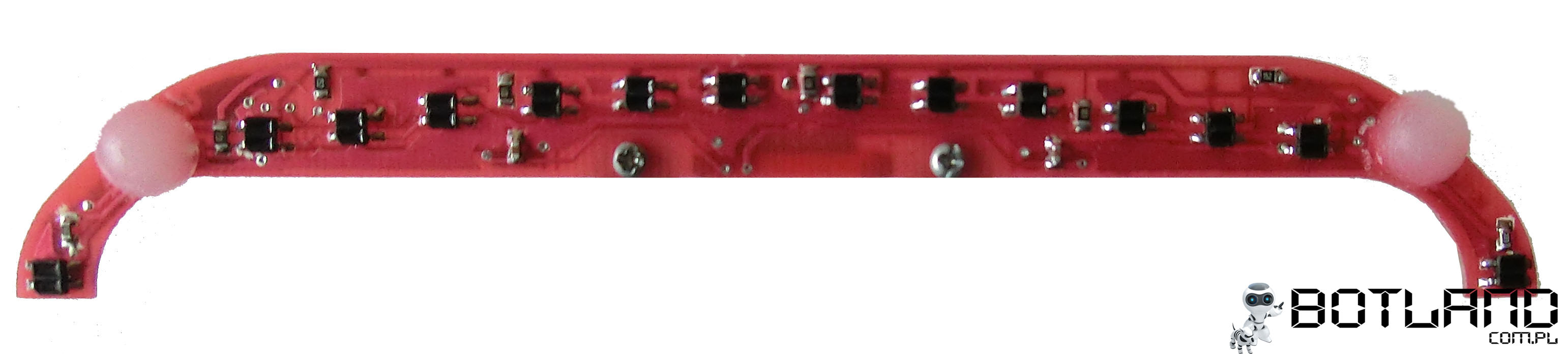
Reflective optocouplers KTIR0711S detect the lines. They were connected in groups of 3 sensors in series with a resistor. Pads for digital distance sensor (40cm) from Sharp were mounted on the PCB.
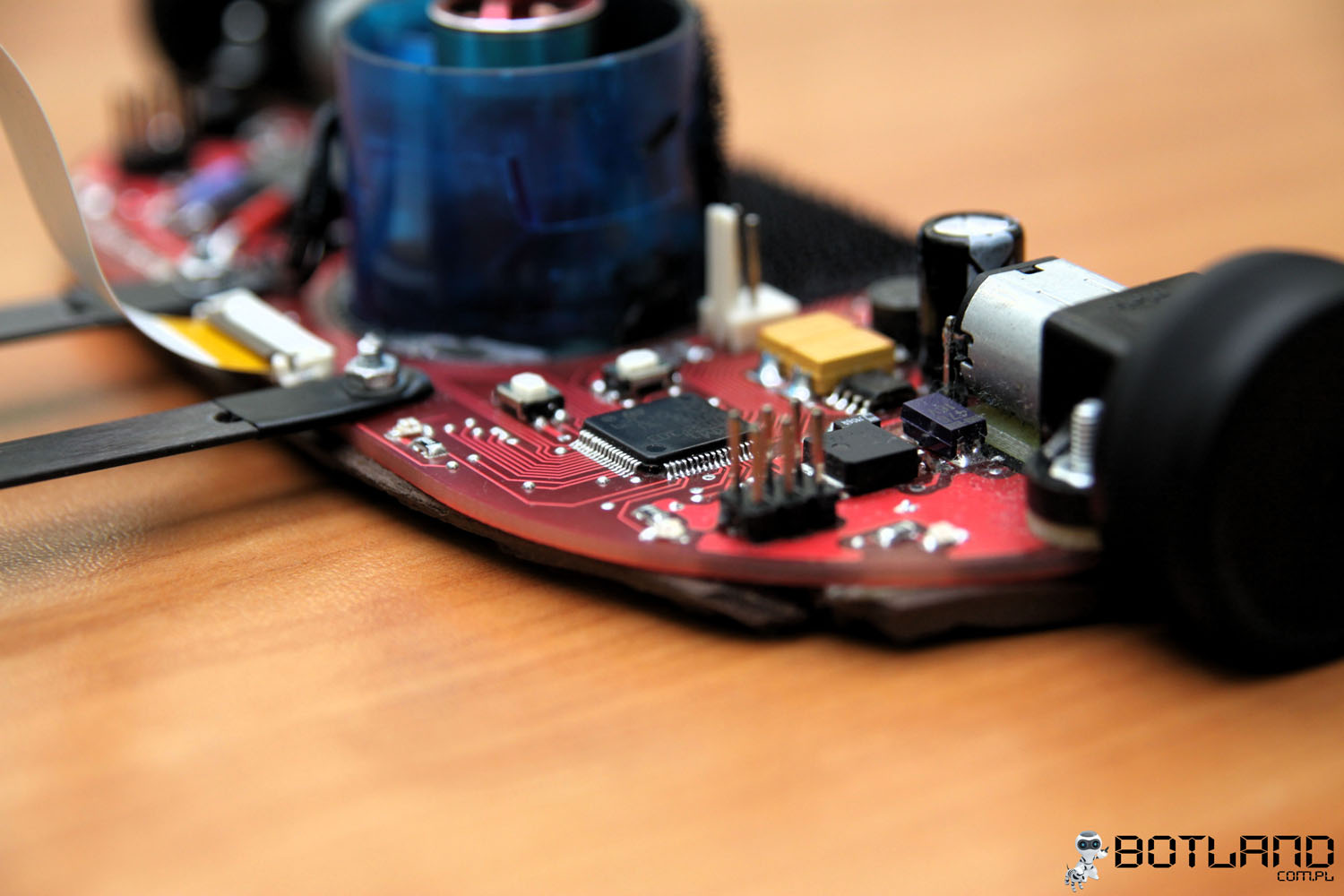
Main module:
The PCB is both the printed circuit and chassis of the construction of vehicle. In addition to electronic systems it is equipped with drive motors and drive tunnel. Size of the module was reduced – its dimensions are: 140x60mm.
Electronics:
The main element is the microcontroller from STM32 family. Engines are controlled by H bridges TB6612. Supply line consists of a pulse converter 5V and linear stabilizer 3,3V.
Microcontroller used is 32-byte STM32F103RBT6 with a core from ARM Cortex-M3, which is equipped with: 128kB Flash, 20kB RAM, USB, CAN, UART, I2C, SPI, ADC, DAC in housing LQFP64, and it can:
- read the states of input ports
- convert analog to digital signal
- generate PWM signal
- control H bridges – generate correct signals
- implement control algorithm
- communicate with LCD module
- control LEDs
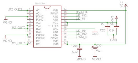
Engines drivers consists of two two-channel H bridges from Toshiba TB6612, which allow to:
- control the rotation speed using PWM signal
- change the direction of engine rotation by changing hte states of two pins
- quick braking
To protect the system against damage when taking the maximum current by engines (1600mA), channels A and B of bridges were connected (current efficiency increased to 2A). Bridges were connected in the way shown in the picture below:
Remote control:
Due to the fact that the line follower reaches high speed, it is difficult to stop the robot manually. Starting and stoping can be done wirelessly, using IR. Attiny13 is responsible for decoding the signal from the remote control, which transmits the signal in standard RC5. Solution from Philips increases the resistance to interference from the environment and makes it possible to use universal and public remotes. Other buttons on the remote control can also be easily used. Additional processor was used because of the high demands on the reliability of the remote stop, for example in emergency situations.
Drive:
Drive consists of two Pololu HP engines with transmission of 10:1 with the following technical parameters:
- RPM at idle when powered by 6V: 3000 RPM
- idle current (6V): 120mA
- peak current: 1600mA
- torque: 0,3kg*cm (29 mNm)
- dimensions: 24x10x12mm
- weight: 10g
Wheels were made of rims milled of plastic polyamid and specially selected tires. Rim is tight-fit onto the motor shaft and secured with cyanoacrylate adhesive, as shown in the picture below:
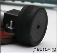
This vehicle uses the same tires as in Mini-Z car models. They are 12mm wide and 3mm thick. Another parameter is the hardness 20 degrees (in a range of 10 to 60). Tires with lower hardness are characterized by increased adhesion, however they wear out more quickly. Wheel and tire diameter is 27mm. It is also important to clean the tires before each drive of the vehicle to remove dust particles, which causes loss of the adhesion and have a negative effect on performance of the robot.
Theoretical maximum linear speed of the line follower is about 3m/s. Depending on the route, reached medium speed is 2,3-2,5m/s.
Tunnel drive:
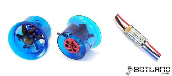
Another important element is the EDF tunnel drive. It consists of a turbine (the same as used in flying models, but mounted reversively). That element is to produce additional downforce, which helps the robot to stay on the road when cornering at high speeds (over 2m/s). The turbine is equipped with a brushless motor (11000 RPM, current consumption about 4A), which is controlled from Dualsky company.
Tunnel drive EDF27 with engine controller:
Supply:
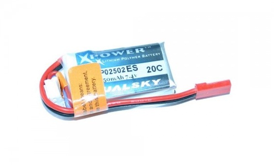
The robot is supplied from Dualsky Li-Po package 220mAh 25C 7,4V. Continuous current provided by this package is 5,5A, while the peak is 11A, which is more than enough to supply the device. The accumulator allows for about 30 seconds of optimal drive, after which power voltage drops which negatively affects the dynamics and speed of the robot. The package showed in the picture below weighs only 16g.
Engines and tunnel drive are supplied directly from the accumulator. Electronic elements requiring 5V are powered by stabilized voltage using adjustable converter ST1S10PHR with a current efficiency up to 3A. Supply of the processor (3,3V) comes from linear LDO (low-dropout) LF33CT, whose input voltage comes from 5V converter. The following picture shows the schematic of power:

User's interface:
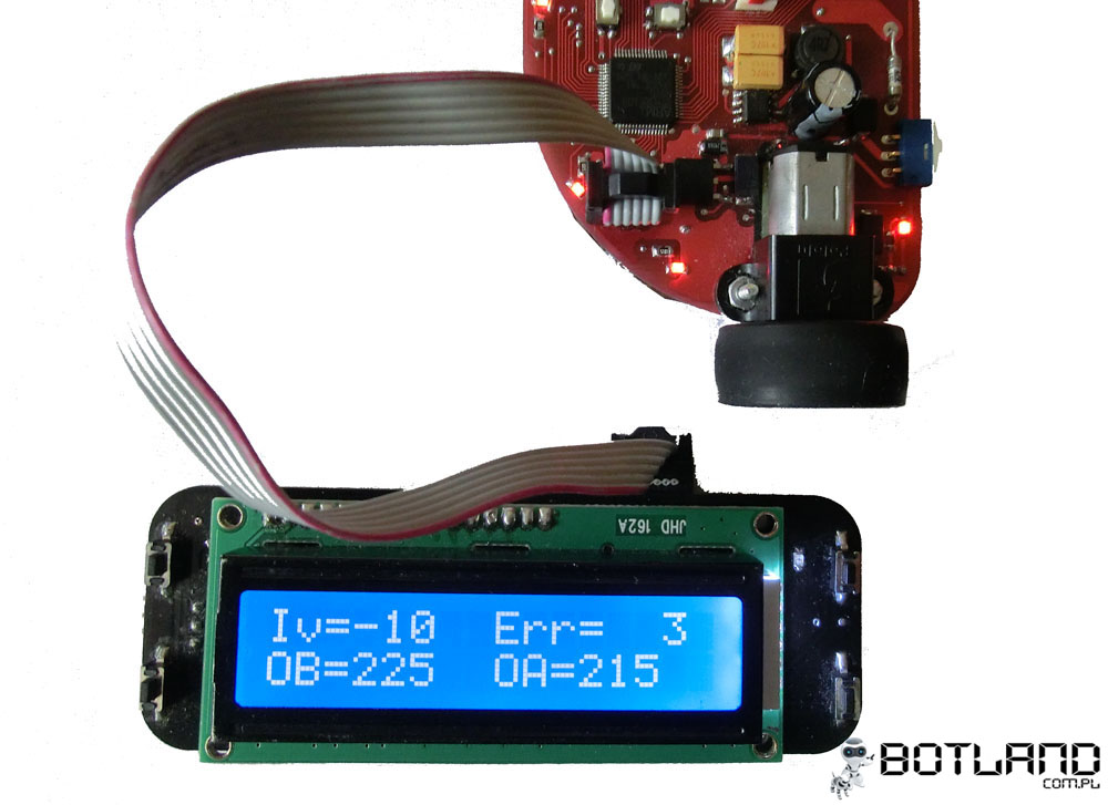
Setting the controller requires often changes of parameters such as: maximum rotation speed of the driving engines, speed of turbine rotor or PID controller gain. Module with LCD display for viewing the serrings and buttons for adjustment is a convenient solution in this vehicle. The system is a separate module, which connects with the robot by UART interface.
Main functions of the module:
- selection of controller settings
- selection of maximum speed
- selection of RPM of the tunnel drive turbine rotor
- checking whether the sensors operate correctly
- pewview of the output data of the PID controller
- setting the threshold voltage value for reflective sensors
Software:
Software was written in C using libraries from STM: STM32F10x_StdPeriph_Lib_V3.5.0. Control algorithm is PID with some modifications.
Pictures:
Videos:
Link to original thread (useful attachment) - Line Follower Impact