Continue to Site

Welcome to EDAboard.com

Welcome to our site! EDAboard.com is an international Electronics Discussion Forum focused on EDA software, circuits, schematics, books, theory, papers, asic, pld, 8051, DSP, Network, RF, Analog Design, PCB, Service Manuals... and a whole lot more! To participate you need to register. Registration is free. Click here to register now.

Using a PIC as Channel Select Device.

Status
Not open for further replies.

tait 700

Junior Member level 2
Joined
Apr 20, 2012
Messages
20
Helped
0
Reputation
0
Reaction score
0
Trophy points
1,281
Activity points
1,518
Hi,

Was wondering if someone could tell me if the following was possible using a PIC as the main component ?

I have a Radio receiver that uses 7 input lines to select its various preprogrammed channels in its main Eprom. These lines are switched either Logic High or logic low in various combinations, eg. Channel 4 has 5 lines at Low and 2 lines at High Level, Channel 8 has 6 lines at low and 1 at High.

There are 15 different combinations of the 7 lines either High or low ( 15 Channels ). The system uses Dip switches that ground each line to manually select the correct channel in a preselect operation, and uses the changing logic states of the lines when the External channel selector is being used.

My ideal solution would be if i could have one momentary switch that when operated caused the PIC to go up one channel at a time switching each of the 7 lines either high or low as instructed by its program. Either that or a two way momentary switch that could go up the channel list or down the channel list depending on which way the switch was operated.

The lines have to remain stationary once selected and the PIC is taking the place of the Dip switches sending each line either high or low.

If it was possible to have some form of indication, either a LCD or Twin 7 Seg LED that displayed what was selected by the PIC, would be a big help.

Any info on the above would be most appreciated, i have little knowledge of this topic but it seems to be the easiest way to achieve a solution to this problem if it is possible.

Regards,

Chris S.
 

Any microcontroller could do it. By the way, it is also possible to buy rotary, or thumbwheel switches, that can have binary output - then you don't need a microcontroller and display. Some even come with up/down switches and a little mechanical numerical display. You'd need two of them. They are probably not cheap, but might work out cheaper if you factor in your time.

EDIT: I saw **broken link removed**, which is $17 each, I expected a higher price to be honest.
I didn't look to see if there are cheaper ones, there possibly are.

EDIT2: That's a price for 6, not 1. That's an excellent price : )
 
Thanks Sky,

Could you explain how those switches would be able to switch the lines either high or low ?

For example Channel 5 has the following,

1. = low
2. = low
3. = high
4. = low
5. = low
6. = low
7. = low

If there was a way they could select the correct lines either high or low themselves that would be great.

Very good price indeed.

Cheers,

Chris S.
 

From what you're saying, channel 5 seems to correspond to binary 4, so I'm guessing channel 1 is binary 0 for example.
chan1 = binary0 = 0000000
chan2 = binary1 = 0000001
chan3 = binary2 = 0000010
chan4 = binary3 = 0000011
chan5 = binary4 = 0000100
etc..

Each switch will have 5 connections, one is a common (e.g. to be wired to ground, or to wherever one side of the DIP switches currently
connects to) and the other four will go to the other side of where the current DIP switch go to.
That will take care of 4 input lines, and then you need a second switch for the remaining three lines (no need to use one of the connections from the second switch).
Then, you can select by pressing up/down on either of the switches. The left switch can be set to any value between 0 and 7, and the right switch can be set to any value (it will be between 0 and 15).

You could label the left switch "bank" and right-switch "channel" for instance, so that you have eight banks (0-7) of 16 channels (0-15) each.

If you wanted to, you could make the left switch repeat on banks 8-15 (rather than remaining unused), so that bank 8 is the same as bank 0 for instance.

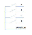
The quick sketch here shows what is inside each switch:
hex_switch.jpg
Basically, it consists of four switches internally, and when you press the up/down buttons, the switches operate in the binary sequence. (I'm guessing they have a cam or some circular circuit board with arcs etched with the binary sequence, and some metal wiper contact). In other words you can use the switch to represent 2^4 (i.e. 16) states (binary 0 to 15).
 
Last edited:
128 Channel.JPG

Thanks Sky,

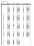
Attached is the Programming sequence for the Onboard Eprom in the radio.

( 1 ) is 0v grounded to chassis of radio,

( 0 ) is 4.9V using pull up resistors to keep line High.

These are with the Dip switches open, i.e, using external device to select channel lines.


I will print out what you have said and study it, this sounds the way to go and when i have my head around it i will go with this idea.

Thanks again for your help,

Regards,

Chris S.
 

Thumbwheel switches can be obtained in hexadecimal (16 position, they read A to F after 9) with a 4-bit binary output. You could use just one of these for your purpose. (assuming you only need channels 1 to 15 on your chart).
 
No problem, hope it goes well.
Here's a rough sketch to help.
It looks like the first connection on the switch is COMMON, but you may need to double-check with the physical switch (I may have got the ordering back-to-front). It's easy to confirm with a multimeter set to continuity check.

I assumed that the top row of pins on the DIP switch are all connected together, and also that the leftmost DIP switch does nothing, but basically you'll see that easily on the PCB and adjust accordingly.
Notice the "bank" switch uses A, B and C connections, and not D, which is left unconnected. If the bank switch is set to '8', then it will give the same result as bank '0', '9' will give the same result as '1' and so on.
switch_arrangement.jpg
 
Thumbwheel switches can be obtained in hexadecimal (16 position, they read A to F after 9) with a 4-bit binary output. You could use just one of these for your purpose. (assuming you only need channels 1 to 15 on your chart).

Thank you Sir,

Will probably go this route as it seems the most simple way to do it.

Cheers,

Chris S.

- - - Updated - - -
 

Status
Not open for further replies.

Part and Inventory Search

Welcome to EDABoard.com

Sponsor

Back
Top