Continue to Site

Welcome to EDAboard.com

Welcome to our site! EDAboard.com is an international Electronics Discussion Forum focused on EDA software, circuits, schematics, books, theory, papers, asic, pld, 8051, DSP, Network, RF, Analog Design, PCB, Service Manuals... and a whole lot more! To participate you need to register. Registration is free. Click here to register now.

Help With My First LM13232AFW GLCD Project

Status
Not open for further replies.

hesho90

Member level 4
Joined
Sep 3, 2012
Messages
78
Helped
0
Reputation
0
Reaction score
0
Trophy points
1,286
Location
egypt
Activity points
1,778
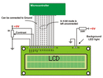
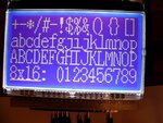
i just got new Glcd lm13232afw and 16f877a

i dont know what pins of the lcd i have to wire with the pic to make aa code and its now on proteusi made a new one with all if its pin shoud make them all passve or it will make no deffrent

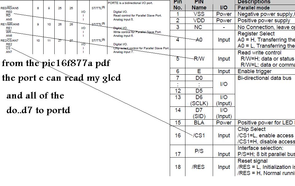
the pins i see on the lcd datasheet are

VSS VDD NC A0 NC E D1 D2 D3 D4 D5 D6 D7 BLA /CS1 P/S RES

WHAT of those pins i wire with portb and sould i make like

sbit LCD_EN at RB1_bit; or sbit GLCD_EN at RB1_bit;

View attachment LM13232AFW.rar
i attachments the lcd data sheet
 

Re: i have a lot of Qs plz help me with my lcd

you can comunicate with this LCD Serial or Parall as flow:
sch.JPG
 

Re: [Moved] i have a lot of Qs plz help me with my lcd

sch1.JPG
but you must current source cabaplity of pin that will drive the Backlight
 
  • Like
Reactions: hesho90

    hesho90

    Points: 2
    Helpful Answer Positive Rating
Re: [Moved] i have a lot of Qs plz help me with my lcd

can you till me how is the code going to be like
 

Re: [Moved] i have a lot of Qs plz help me with my lcd

For code you need to make a choice whether you are comfortable with assembly or C language ?
for the connections, See the circuit below: (just a reference; not exactly matched with yours)
 

Attachments

  • lcd.gif
    lcd.gif
    52.4 KB · Views: 218

Re: [Moved] i have a lot of Qs plz help me with my lcd

For code you need to make a choice whether you are comfortable with assembly or C language ?
for the connections, See the circuit below: (just a reference; not exactly matched with yours)

hello thank you for the replay

i make the code in C language if i can but as you see in the replay abuve you that my lcd pins dont have most commen pins so it hard to regster the glcd so i have to ues it in seril mode but dont know how to regstr that

i dont know what is assembly

the data sheet is attaced
thank you
 

Attachments

  • LM13232AFW.rar
    250.5 KB · Views: 112

help with my 1st Glcd project

hello i have a LM13232AFW and PIC16F877A

and i made my glcd on proteus

بدون عنوان.JPG

i know the pins Connection are good but i dont know how to start a code with that

its a GLCD on mikroc i have tried a lot of things but didnt wark and the help they have dont help with my project i just need a code that good with my glcd or parallel mode dont know how to start that 2
so if you are apro what mode shuld i use and can you give a code makeing help

this the glcd datasheet View attachment LM13232AFW.rar

thank you
 

Hi,

Wow, from doing your first flashing led yesterday you are now onto glcds !!:smile:

There are so many types of glcd, and while their fuctions are similar they need a geat amount of code to get them working.
If you can use a complier that has libraries for that glcd then the problems solved, however the one you have used is not very popular to my knowledge.

I would strongly suggest while you are still starting to learn how to program then use one of the more popular standard LCD, any 16x2, HD447080 compatible like the LM016 in ISIS will do.
Its easy to use and has been the standard display for so many Pic projects.


If you want a micro system that will allow you to run glcds just by loading some existing coded then you prehpas need to look at a different approach.

MikroE do complete systems, compliers and hardware including glcds that will do that, but at a high cost.

The Ardunio system , the software is free and a starter Uno board costs very little;you can be running a glcd in 5 minutes
https://arduino.cc/en/Main/ArduinoBoardUno
 

Attachments

  • 2011-03-07 002.jpg
    2011-03-07 002.jpg
    93.7 KB · Views: 173
  • 2011-03-07 007.jpg
    2011-03-07 007.jpg
    66.5 KB · Views: 161
  • Like
Reactions: hesho90

    hesho90

    Points: 2
    Helpful Answer Positive Rating
Just try the glcd example in mikroC. Also connect MCLR pin to Vcc through 10k resistor.
 
  • Like
Reactions: hesho90

    hesho90

    Points: 2
    Helpful Answer Positive Rating
glcd example in mikroC and they dont help so i go to mikropascel and i make one

program GLCD_Test;


var GLCD_DataPort : byte at PORTD;

var GLCD_A0 : sbit at RE0_bit;
GLCD_RW : sbit at RB1_bit;
GLCD_CS1 : sbit at RE2_bit;
GLCD_EN : sbit at RB6_bit;
GLCD_RES : sbit at RB7_bit;

var GLCD_A0_Direction : sbit at TRISE0_bit;
GLCD_CRW_Direction : sbit at TRISE1_bit;
GLCD_CS1_Direction : sbit at TRISE2_bit;
GLCD_EN_Direction : sbit at TRISB6_bit;
GLCD_Res_Direction : sbit at TRISB7_bit;

var counter : byte;
someText : array[18] of char;

procedure Delay2S(); // 2 seconds delay function
begin
Delay_ms(2000);
end;

begin


end.

but it didnt draw any thing
i already have this lcd befor i can test it on the bread board i have to make it write some thing on porteus
 

glcd example in mikroC and they dont help so i go to mikropascel and i make one


but it didnt draw any thing
i already have this lcd befor i can test it on the bread board i have to make it write some thing on porteus

Which microcontroller are you using?

Can you zip and post your proteus file?

Your GLCD can be used in parallel / serial mode. If P/S is 1 then it is in parallel mode. If P/S is 0 then it is serial mode.
 
Last edited:
  • Like
Reactions: hesho90

    hesho90

    Points: 2
    Helpful Answer Positive Rating
Which microcontroller are you using?

Can you zip and post your proteus file?

Your GLCD can be used in parallel / serial mode. If P/S is 1 then it is in parallel mode. If P/S is 0 then it is serial mode.

i dont know how to make ir 1 or 0 and i like the parallel mode or the one in the photophoto.JPG

and i use PIC16f877a
 

Attachments

  • Glcd test project.rar
    23 KB · Views: 113

I believe the issue maybe that you are attempting to utilize the MikroE GLCD library with a LM13232AFW based GLCD.

I reviewed both the user manual and help system and I see no indication the library routines support the LM13232AFW chipset.

Reference: MikroC Pro for PICs User Manual, Section: GRAPHIC LCD LIBRARY, Page: 326
The mikroC PRO for PIC provides a library for operating Graphic Lcd 128x64 (with commonly used Samsung KS108/KS107 controller).

Reference: MikroC Pro for PICs User Manual, Section: SPI GRAPHIC LCD LIBRARY, Page: 479
The mikroC PRO for PIC provides a library for operating Graphic Lcd 128x64 (with commonly used Samsung KS108/KS107 controller) via SPI interface.

There are several KS108/KS107 compatible controllers available, however I do not believe the LM13232AFW chipset is one of them.

Unfortunately, you will most likely need to either find a third party library which supports the LM13232AFW chipset or write your own routines.

By the way, I was unable to open your Proteus simulation file, what version of the application are your currently using?

BigDog
 
  • Like
Reactions: hesho90

    hesho90

    Points: 2
    Helpful Answer Positive Rating
hello

i understand that mikroc want help so i chang to mikropascel so i have my own routines like post #11

im not sure if they good to wark in till i can make it write any thing i use proteus 7.7 sp2

this what i get in till now so it wark with my pic


if you can give me a head start abut how my own routines going to be in code
 

i understand that mikroc want help so i chang to mikropascel so i have my own routines like post #11

I believe the library routines are the same regardless of which programming language you choose.

In other words I don't believe they are compatible with the LM13232AFW chipset.

im not sure if they good to wark in till i can make it write any thing i use proteus 7.7 sp2

this what i get in till now so it wark with my pic


I believe the image shows the pinout for the KS108/KS107 based GLCD, NOT the LM13232AFW based GLCD.


if you can give me a head start abut how my own routines going to be in code

Writing library routines for a GLCD which uses a new controller is quite nontrivial and can be extremely complex, too difficult for a beginning programmer.

I would agree with wp100 and suggest you start off with a simple HD44780 compatible 16x2 LCD.

Lab 4: Interfacing a character LCD

Then after you have master it and you still wish to pursue the GLCD, I would suggest obtaining a KS108/KS107 based GLCD instead of the LM13232AFW based GLCD.

Lab 20: Interfacing a KS0108 based Graphics LCD (Part 1)

Lab 20: Interfacing a KS0108 based Graphics LCD (Part 2)

Be aware the above tutorials are NOT compatible with your LM13232AFW based GLCD.


BigDog
 

you sure there is no way but a controller to make it wark
 

It is possible to write a driver/library routines for the LM13232AFW controller based GLCD, however to give you an example of the complexity of such a task the attached zip file contain the source for the KS108/KS107 controller GLCD.

Details on how to utilize the source code in a typical C language project are provided at the following site:

Samsung KS0108/KS0107 Library Source

The source code I've attached essentially accomplishes the same task as the MikroC Library.

After looking over the attached source code, honestly ask yourself whether or not you are up to the task of writing the source code library for the LM13232AFW controller from scratch/beginning with little or no help.

BigDog
 

Attachments

  • ks0108lib.zip
    10.7 KB · Views: 105

I downloaded the zip file you had previously uploaded and after examining the contents, I found a C source code file demonstrating driver library for the LM13232AFW GLCD.

Within the code I noticed the controller chipset is actually ST7565 controller, NOT the LM13232AFW which is the model number of the GLCD.

The fact that the GLCD uses the ST7565 controller is better news, while driver source code for the ST7565 controller chipset is not as common as driver source code for the KS108/KS107 controller, it does exist.

Code:
//----------------------------------------------------
//
//   ÍØÆÕ΢ÄÚÖÃST7565/67Òº¾§ÏÔʾģ¿éϵÁÐÓ¦ÓóÌÐò°ü-V0.1
//         £¨Ó¦ÓÃÒº¾§ÏÔʾ¿ØÖÆÆ÷[COLOR="#FF0000"]ST7565[/COLOR]/67£©
//
//
//   ±¾ÎļþÊÇÓ¦ÓÃÊÖ²áÖгÌÐòµÄCÎļþ,Óû§¿ÉÒÔÖ±½Ó¿½±´
//   ³ÌÐò²ÎÕÕÓ¦ÓÃÊÖ²áÖÐÁ½ÖÖ²¢Ðнӿڵç·¶¨ÒåµÄ½Ó¿Ú¶Ë
//
//         ÉîÛÚÊÐÍØÆÕ΢¿Æ¼¼¿ª·¢ÓÐÏÞ¹«Ë¾
//      Shenzhen TOPWAY Technology Co.,Ltd.
//
//       by Guo Qiang           2008-11-21
//
//----------------------------------------------------

#include <stdio.h>
#include <reg52.h>
#include <intrins.h>

#define uchar unsigned char // 0~255
#define uint unsigned int   // 0~65535
uchar   ContrastLevel;     // for contrast setting level
...
...
...
...

I found the following source code examples for GLCDs which use the ST7565:

Lady Ada ST7565 LCDs Tutorial

PIC Assembler Code for ST7565 GLCD

ST7565 LCDs: Graphical LCDs!


I also found a MikroC compatible library for the ST7565 controller based GLCDs, the bad news is it is written in Pascal for the PIC32 and would certainly require a rewrite to function with the PIC16F series:

Sitronix ST7565 LCD driver

BigDog

- - - Updated - - -

Do you purchase parts from this site?

Ram Electronics

If so, this is the display I would recommend:

**broken link removed**

The LM12864LFW GLCD uses the S6B0108B controller chipset, which is actually a KS108/KS107 compatible chipset.

The LM12864LFW GLCD should allow you to use the existing MikroC GLCD libraries and should be compatible with the example projects/tutorials I previously posted in reply #16.

BigDog
 

Status
Not open for further replies.

Part and Inventory Search

Welcome to EDABoard.com

Sponsor

Back
Top