Continue to Site

Welcome to EDAboard.com

Welcome to our site! EDAboard.com is an international Electronics Discussion Forum focused on EDA software, circuits, schematics, books, theory, papers, asic, pld, 8051, DSP, Network, RF, Analog Design, PCB, Service Manuals... and a whole lot more! To participate you need to register. Registration is free. Click here to register now.

Power Dissipation Across Resistor

Status
Not open for further replies.

habibparacha

Junior Member level 2
Joined
Oct 25, 2010
Messages
24
Helped
1
Reputation
2
Reaction score
1
Trophy points
1,283
Activity points
1,482
Hi,

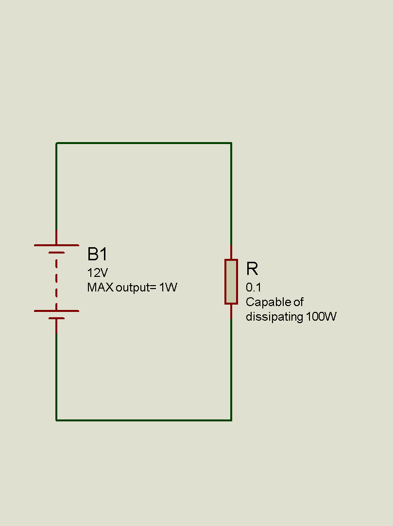
A theoretical Question. I have a battery and a resistor attached in series. Battery is 1V(maximum power it can diliver is 1W) and the resistor is 0.1Ohm(Capable of dissipating 100W). What will be the voltage and current across the resistor.

If we calculate by the power supplied by the battery than V=IR (Ohm's law fails) and otherway around KVL fails. Any help will be appreciated.
 

if there is no other element in the ckt then the current in the ckt is 10 A

power dissipated =V^2/R = 1/(.01)= 10 W

never in the ckt the power disspated in the load resistance drops below 10W

- - - Updated - - -

provide a schematic for furthur reference there is some thing missing here
 

Don't forget the internal resistance of the battery.
 

but that can only increase the power op by the battery right

there is some thing which we are missing here @habibparacha has to post the missing link
 

This is a theoretical Question no real world equipments are used here is the circuit diagram:


- - - Updated - - -

if there is no other element in the ckt then the current in the ckt is 10 A

power dissipated =V^2/R = 1/(.01)= 10 W

never in the ckt the power disspated in the load resistance drops below 10W

- - - Updated - - -

provide a schematic for furthur reference there is some thing missing here

If Power is 10W than where is this power coming from the battery is supplying only 1W.
 

yup my mistake that was increase power dissipated out to the surrounding

but 10 W and 1W
 

If the battery can deliver 1W, we can can calculate the internal resistance:
https://en.wikipedia.org/wiki/Maximum_power_transfer_theorem

Delivered power = 1W at Rsource=Rload
and voltage across Rload = 1/2 Volt

Pload = Vload^2/Rload ---> Rload = Vload^2/Pload ---> Rload = 0.5V^2/1W = 0.25 Ohm
and because in this case Rsource = Rload
---> internal resistance of the battery Rsource = 0.25 Ohm

How is the Voltage across Rload =0.5V it will be only in the case when Rload = Rsource but you have calculated Rsource to be 0.25Ohm while Rload is 0.1 Ohm. What will be the current flowing in the circuit.

According to my knowledge I think the Current will be 10A which means that 10W will be required which the battery is unable to supply that is why the voltage drops to 0.1V to keep the power at 1W.
 

How is the Voltage across Rload =0.5V it will be only in the case when Rload = Rsource

Yes. That is the case with specified max power (1 Watt) delivered to the load.

but you have calculated Rsource to be 0.25Ohm while Rload is 0.1 Ohm. What will be the current flowing in the circuit.

You can easily calculate that. Voltage source 1V, total resistance = 0.25 Ohm + 0.1 Ohm.
 

other than that there is a violation of maximum power transfer theorem that makes it not possible for more than 1W be dissipated

PS thanks for opening my eyes pal had conceptualised completely wrong
 

I doubt that it's of much use to guess about the battery. There should be a clarification first.

- Trivial point. The battery voltage is said to be 1 V in post #1 and 12 V in post #5. What's right?
- does max. output 1W define an internal resistance? Although it's a usual specification for RF, it's rarely used for DC sources (except for specification of intrinsic safe circuits).
 

I doubt that it's of much use to guess about the battery. There should be a clarification first.

- Trivial point. The battery voltage is said to be 1 V in post #1 and 12 V in post #5. What's right?

Sorry the Image in post #5 was drawn in hurry so that's why its actually a 1V battery
 

In this case, you should draw an equivalent circuit that shows the internal battery impedance. It will hopefully help to clarify the circuit behaviour.
 

I doubt that it's of much use to guess about the battery.

I think that with 1V battery and 1W max, this is student's homework and not related to a real circuit problem.
 

Status
Not open for further replies.

Similar threads

Part and Inventory Search

Welcome to EDABoard.com

Sponsor

Back
Top