Continue to Site

Welcome to EDAboard.com

Welcome to our site! EDAboard.com is an international Electronics Discussion Forum focused on EDA software, circuits, schematics, books, theory, papers, asic, pld, 8051, DSP, Network, RF, Analog Design, PCB, Service Manuals... and a whole lot more! To participate you need to register. Registration is free. Click here to register now.

AC Lamp Dimmer Using TRIAC and PIC16F877A

Status
Not open for further replies.

Jestin_cubetech

Advanced Member level 1
Joined
Jun 24, 2012
Messages
499
Helped
76
Reputation
152
Reaction score
73
Trophy points
1,328
Activity points
3,697

- - - Updated - - -

Code:
#include <pic.h>                                              //triac light dimmer   
#define _XTAL_FREQ 20000000

#define TRIAC1 RB3        
#define UP  RB7 
#define DWN RB6 

#define MAX_TIME 3500
#define MIN_TIME 1

int k=0,dly=0;

void interrupt isr()
{
///////////////////////////////////// 
if(INTF)
{
INTF=0; 
while(!RB0); 
dly=k;
while(dly--); 
TRIAC1=1;
#asm
nop;nop;nop;nop;nop;nop;
nop;nop;nop;nop;nop;nop; 
nop;nop;nop;nop;nop;nop;
#endasm
TRIAC1=0; 
}
}
/////////////// MAIN //////////////////////
void main()
{
 TRISD=0x0; TRISB=0xF1;
    
   k=300;
 INTE=1; INTEDG=1;    PEIE=1;GIE=1;

while(1)
{
if(!UP)
{
__delay_ms(100);  
if(!UP)
{
  if(k>=MAX_TIME) k=MAX_TIME; k++;  
 dly=k;
}   
} 
 else if(!DWN)
{
__delay_ms(100);
if(!DWN)
{
   if(k<=MIN_TIME) k=MIN_TIME; k--;   
 dly=k;
}
} 
 }
}
/////////////////////////////////////////////////
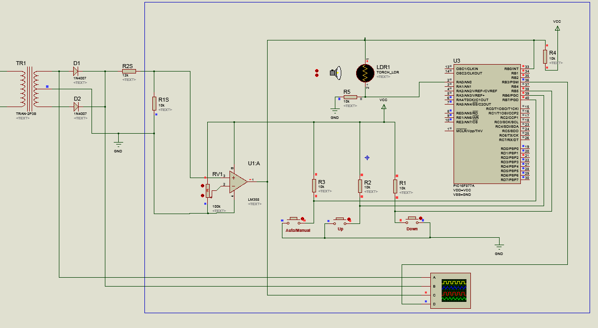
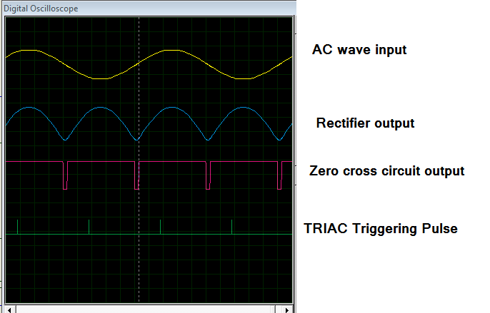
25_1347338499.png


81_1347338499.png
 

Hello, I'm working on quiet similar project with this but I use ATmega8535 instead of PIC. Actually I want my circuit work automatically dimming the lamp based on the input of the LDR. Can you guide me please? I really need your help coz I don't have much experiences in this one.

Thank you.
 

Code:
steps
1, read LDR value  using ADC
2, PID   [optional]   
3, set ADC data is dly value [see the program:    TRIAC Firing delay ] 
    ADC data should be scaled 

   #define MAX_TIME 3500
   #define MIN_TIME 1

4, in a brighter light environment LDR reading will be low [as per the LDR circuit ],smaller ADC value means   smaller delay  from zero crossing to TRIAC firing.

_5v___
|
\
/
\ 10K
/
|
. ----------------------------> RB0
|
|
|
| |
|LDR|
| |
|
|
|
GND
 

Thank you for your reply. Well can you tell me the dimming circuit ? I mean the connection between microcontroller up to the lamp and the zero crossing circuit? I really confuse with AC.
 

Great!!!
Can you give some explanations of this project ?
I need references to build AC lamp dimmer and it was using LDR too.
and how exactly your dimmer circuit is?


TRIAC interface circuit
 

Attachments

  • CubeTech.jpg
    CubeTech.jpg
    36.6 KB · Views: 286

Jestin , please could you upload the full MikroC code and the Protues file ? thanks alot
 

Well, what is the function of

#define MAX_TIME 3500
#define MIN_TIME 1

I'm using AVR, is it the same?
 

it depends on the delay_function. while(dly--);
AVR is faster than PIC,so you need to adjust that value.
 

Ok, just ignore the LDR first. This is my code to dim the lamp (50%). (using codevisionavr) ATmega8535

Code:
#include <mega8535.h> 
#include <delay.h>
bit ZC;

// External Interrupt 0 service routine
interrupt [EXT_INT0] void ext_int0_isr(void)

 {
    ZC=1;
 }

// Declare your global variables here

void main(void)
{
PORTA=0x00;
DDRA=0x00;

PORTB=0x00;
DDRB=0xFF;

PORTC=0x00;
DDRC=0xFF;
 
PORTD=0x00;
DDRD=0x00;

// External Interrupt(s) initialization
// INT0: On
// INT0 Mode: Falling Edge
// INT1: Off
// INT2: Off
GICR|=0x40;
MCUCR=0x02;
MCUCSR=0x00;
GIFR=0x40;
  
// Global enable interrupts
#asm("sei")

while (1)
      {
        if(ZC==1)
        {PORTB=0x00;
        delay_ms(5);  // firing triac 5 ms after zero cross detected to get 50% brightness
        PORTB=0x01;   
        delay_us(10);  // firing pulse width 10us
        PORTB=0x00;
        ZC=0;
        }  
      }
}

when i tested it into the hardware, i see in the oscilloscope that the delay is not 5ms, it much longer than 5 ms and i got a blinking lamp. Whats wrong here?
 

Code:
#include <pic.h>                                             //XMAS    STAR-    20 MHZ CLOCK
#define _XTAL_FREQ 20000000

#define TRIAC1 RD2     
#define MIN_TIME 1
#define MAX_TIME 4500
int k=1,dly=1;
/////////////// MAIN //////////////////////
void main()
{
int j=-10;
unsigned int cnt=0;
k=4500;	
TRISD=0xF0; TRISB=0xff;   TRIAC1=0;  
while(1)  
{
while(RB0);
{
if(k>4500){ j=-10;}   if(k<1){  j=30;}  k=k+j;  

dly=k; while(dly--);
TRIAC1=1;
while(!RB0); 
#asm
nop;nop;nop;nop;nop;nop;
nop;nop;nop;nop;nop;nop; 
nop;nop;nop;nop;nop;nop;
#endasm 
TRIAC1=0; 
}

}

}

this is a simple working program for dim and bright Christmas star..
 

Jestin,

I hope that this does not get posted twice, as I tried this earlier tonight but did not see it show up in the threads.

I have several questions about your TRIAC interface circuit. I am trying to build a circuit that is very simular, except that it will primarly use 120V 60Hz. It is fine if it works for 120/230V and 50/60Hz. The incandescent bulb will be no more than 75W.
My first question is about the MOC3021 and MT136 devices. There seems to be several varities, especially with the MT136. Is there specific ones that you would recommend?
What are the wattage rating of R1, R2, and R3? Are they 1/4 watt or 1/2 watt?
What gauge wire are you using for the main power?
Would it be easily adaptable to have the output go to an outlet and then plug the corded light into the outlet?
The input to the circuit is coming from a microprocessors PWM. Is the triac triggered off the positive or negative portion of the waveform?

Any other information would be greatly appreciated.
 

correct circuit


- - - Updated - - -

http://obrazki.elektroda.pl/2250358200_1385025158.jpg
 

Jestin thanks for uploading your project with code! I wanted to know, in ISR how did you calculated the"asm-nop" to be added? I am working on speed controlling of ceiling fan.
 

Hi Jestin ,
I am doing the same project what you have done. I am getting the all the output wave form by your code, but the bulb is not get up or down?
The switch is not working? I don't know what is the problem in it? pls help me
Thank you
 

Great work Justin
post the proteus file for this project. bcoz i am trying same thing but i didn't found some component.
 

Status
Not open for further replies.

Part and Inventory Search

Welcome to EDABoard.com

Sponsor

Back
Top