Continue to Site

Welcome to EDAboard.com

Welcome to our site! EDAboard.com is an international Electronics Discussion Forum focused on EDA software, circuits, schematics, books, theory, papers, asic, pld, 8051, DSP, Network, RF, Analog Design, PCB, Service Manuals... and a whole lot more! To participate you need to register. Registration is free. Click here to register now.

Electronic circuit that will make two consecutive switches when it's turned on.

Status
Not open for further replies.

aleks2x

Newbie level 6
Joined
Sep 6, 2012
Messages
14
Helped
0
Reputation
0
Reaction score
0
Trophy points
1,281
Activity points
1,428
Hello all,

I would like to know if there is some simple electronic circuit to make two consecutive switches when it's turned on.
In order to understand better what i actually want to achieve is that i would like to connect this circuit to an air conditioner remote control so it can automatically turn on the AC after a power outage. The first switch would set the remote control to an off state and the next switch would turn on the AC. It might sound silly but i think that that will work.
Any other ideas are welcome.

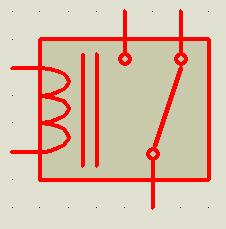
It doesn't have to be made of all active components, i guess that i can also use a 12V DC relay switch?

Thanks in advance,

Aleksandar
 

hi,
just for better understanding of the problem , after a power outage passes, does the air conditioner automatically turn on ? and you want a circuit which automatically puts it beck in to stend by state after the power comes beck?
 

Any relay has two pins which is- either high or low when relay is activated.
Use one pin for remote, other for AC. Only one will be on at a time.
50_1347191846.jpg
 

hi,
just for better understanding of the problem , after a power outage passes, does the air conditioner automatically turn on ? and you want a circuit which automatically puts it beck in to stend by state after the power comes beck?

Thanks for the fast reply.

The Air Conditioner is only turned on by the remote control and it does not have the auto restart feature when the power comes back.
My original idea was to solder the switch pins of the DC relay to the power button of the remote control and plug the wanted circuit(the one containing the DC relay) to the AC Outlet. Here is my situation explained in detail

1. Let's say that the air conditioner is turned on and the remote control is in ON state.

2. When the power goes out, the Air Conditioner shuts off, but the remote control (which is powered by batteries) stays in ON mode.

3. When the power comes back, if there is only one click on the power button, the remote control will go in OFF state and it wont turn on the air conditioner.
4. So another click on the remote control will turn on the air conditioner and the remote control will stay in ON state until the next power outage where the above scenario will repeat.

I hope i explained it right :(

Thanks again
 

Any relay has two pins which is- either high or low when relay is activated.
Use one pin for remote, other for AC. Only one will be on at a time.
50_1347191846.jpg

Genovator,

Thanks for the tip, i think i can implement this on the remote control.
Can you just give me a guide how to make it click only once and then go back to off state? I am talking about the DC relay.

Thank you
 

Hi aleks2x,
Can you please elaborate the line
how to make it click only once and then go back to off state?
..

What logic you are trying to make exactly???
 

Hi aleks2x,
Can you please elaborate the line ..

What logic you are trying to make exactly???

Genovator,

Ignore the previous reply, i think that this will work, i only have another question.
Is there a possibility for the relay to be damaged if there is constant load on it for a long time?

Thank you.
 

hi ,
the relley will not be damaged if the current that flows thru it's contact (and pins) is at nominal or below the nominal value . (inscriptioned on the rellay )
 

hi ,
the relley will not be damaged if the current that flows thru it's contact (and pins) is at nominal or below the nominal value . (inscriptioned on the rellay )

Thanks,
How about the load on the electromagnetic coil? I am talking about the DC load. I am thinking about using 12 dc powered relay.
 

The relay will not damage.
The coil will be shunted to ground by one side with 12v dc on other side. Therefor there will be a constant flow of current through the coil and the coil will always be magnetized. The power consumed by the coil is proportional to the resistance and magnetic flux wasted. A dc relay is usable for you.
 

it is ok, if it is a 12 V dc relley, it will work ok since it is its nominal voltage.
Ps: i drawn a circuit that could be good for you
1puls_rell.AC.on.jpg
It sould work like this: whwn ac goes out the caps discharge on the 1 k rezistor, when ac comes beck, for a tranzitory moment current passes thru the the 100uF cap and the relley clamps once, since dc does not pass thu condensator the relley does not stay energised .
You have to experiment with rezistor and capacitor values so that you get the best RC time caracteristic for your application. The transformer should be 220/9 v (or 220uf insted of the 1000uf cap from the filter)
 
Last edited:
As per your elaboration in post #4, it seems you want to make a logic that whenever mains power goes out, your remote will be turned off until you click power button twice??? Am I right??
 

As per your elaboration in post #4, it seems you want to make a logic that whenever mains power goes out, your remote will be turned off until you click power button twice??? Am I right??

Genovator,

I hope i can explain this right :)
My logic was that when there is ac power present and the air conditioner is on, the remote control should also be on. This is the initial state.
When the ac power goes out, logically the air conditioner will shut off but the remote control will stay in on state as previous (Because of the batteries). Up to here there isn't any kind of intervention from the circuit that i wanted to build.
I wanted to activate the circuit when the power comes back, so when the power comes back i wanted to make the relay clamp once in order to make the remote control go to OFF state (which is equivalent to a person pressing the ON/OFF button on the remote) and lets say after one second make it clamp again (again equivalent to a person pressing the ON/OFF button on the remote) so it can go to ON state and by that it will actually turn on the Air Conditioner. And after this we are back to the initial state until the power goes off and comes back again.
When i thought of this idea i wanted to use only two pins of the relay switch (without using the state when there is no power to it). That's why i wanted the relay to act as a click, and not to stay in the same position until there is power supplied to it.

Now i realize that this is actually pretty complex scenario because you guys gave me the idea to use both states of the relay.

I am thinking to make it pretty simple using ac/dc adapter and a relay.
So now starting from the initial state, when the power goes out, the remote will go in OFF state using the second state of the relay (no power to it). This will be equivalent to a person constantly holding the power button of the remote control. After this, when the power comes back, the relay switch will transit to the first state (there is power supplied to the coil) and will in fact turn the remote control to ON state, which will eventually turn on the Air Conditioner. Again, the relay will act as a person constantly holding the power button of the remote control.

I just don't know if there is a possibility to damage the remote control because it it will be constantly pressed until the power goes out or comes back.

I hope this time i explained my problem :)

Thanks
 

Yes yes.... Now I understand what you wanted to make. :cool:
But since your remote is a wireless device, do you want to make a hard-line connection with it to check if there is power in mains??? Your remote have to know if there is power in house or not. Then, when power comes back, it will delay for say 1 sec and give signal to turn on AC.
How will you make your remote to know? By hard wire, or by wireless?
I dont think your remote casing will have enough amount of space for these additional circuits.
 

it is ok, if it is a 12 V dc relley, it will work ok since it is its nominal voltage.
Ps: i drawn a circuit that could be good for you
View attachment 79943
It sould work like this: whwn ac goes out the caps discharge on the 1 k rezistor, when ac comes beck, for a tranzitory moment current passes thru the the 100uF cap and the relley clamps once, since dc does not pass thu condensator the relley does not stay energised .
You have to experiment with rezistor and capacitor values so that you get the best RC time caracteristic for your application. The transformer should be 220/9 v (or 220uf insted of the 1000uf cap from the filter)

zsolt1,
Thanks for the circuit, i think this is a good start.

- - - Updated - - -

Yes yes.... Now I understand what you wanted to make. :cool:
But since your remote is a wireless device, do you want to make a hard-line connection with it to check if there is power in mains??? Your remote have to know if there is power in house or not. Then, when power comes back, it will delay for say 1 sec and give signal to turn on AC.
How will you make your remote to know? By hard wire, or by wireless?
I dont think your remote casing will have enough amount of space for these additional circuits.

Hmm, you know that i didn't thought about that. You are probably right, there should be at least a second delay before the remote control fires. I think i can modify and implement zsolt1 design.

I wanted to use this for a small server room with couple of servers inside. The air conditioning is always on, so i don't actually need to move the remote control and there is no need to put the components inside the remote.
Well I am assuming because both the remote control circuit and the Air conditioner will be on the same AC source whenever there is power loss actually the remote will go in OFF state, so will the air conditioner because of the power loss. That's why i thought that there is no need for the remote control to know when there is power loss.

Do you think that there is some scenario that this might not work?

Thanks again guys
 

hi again,
a 2 nd idea stroke my mind .... hehe
relley2.JPG
i do not know if it is good for your case .... you will know
It should work like this : when ac mains is present (relley energised) everything is ok, when ac mains disappairs nothing is on (since relley de-energises, and dc equipment has no more power supply from batery) .When ac comes beck again the relley clamps and powers up the dc equipment (which should go on in reset state)
best regards,
z1
 

hi again,
a 2 nd idea stroke my mind .... hehe
View attachment 79949
i do not know if it is good for your case .... you will know
It should work like this : when ac mains is present (relley energised) everything is ok, when ac mains disappairs nothing is on (since relley de-energises, and dc equipment has no more power supply from batery) .When ac comes beck again the relley clamps and powers up the dc equipment (which should go on in reset state)
best regards,
z1

zsolt1,

Considering the fact that this circuit will have its own power supply which will be plugged to the AC outlet, can you make the relay go to ON state (power supplied to the coil), lets say 1 second after the ac power comes back?
I am guessing it will be something with a capacitor?
Thanks,
 
Last edited by a moderator:

So, as per your illustration, i made this theoretical layout...


The control unit will be controlled by a small microcontroller for easy implementation, lesser space, zero maintenance, and logical delay or other safety issues.

This what you want????
 
So, as per your illustration, i made this theoretical layout...


The control unit will be controlled by a small microcontroller for easy implementation, lesser space, zero maintenance, and logical delay or other safety issues.

This what you want????

Exactly what i need Genovator! Is it a complex circuit?
 

Not so much... I suppose you have some knowledge about microcontrollers??? Neither I have a complete knowledge, but can make simple designs. This one seems to be very simple. Tomorrow I will write a program for this. Its late night 12 over here and I have to take a nap :grin:.


I will start from tomorrow.
gd nit..
 

Status
Not open for further replies.

Similar threads

Part and Inventory Search

Welcome to EDABoard.com

Sponsor

Back
Top