Continue to Site

Welcome to EDAboard.com

Welcome to our site! EDAboard.com is an international Electronics Discussion Forum focused on EDA software, circuits, schematics, books, theory, papers, asic, pld, 8051, DSP, Network, RF, Analog Design, PCB, Service Manuals... and a whole lot more! To participate you need to register. Registration is free. Click here to register now.

+40V 0v -40v / 10A SMPS For Power Amplifier

Status
Not open for further replies.

Jestin_cubetech

Advanced Member level 1
Joined
Jun 24, 2012
Messages
499
Helped
76
Reputation
152
Reaction score
73
Trophy points
1,328
Activity points
3,697
i need a 40V /10 A SMPS for Audio Power Amplifier. [MOSFET Bridged Power Amplifier ]

Input voltage : 200- 250 VAC / 50Hz
Output Voltage : +40V 0v -40v / 10A [ Dual Power Supply ]
SMPS Topology : Half- Bridge - MOSFET

Anyone can help me ?
 

Have you studied the half-bridge topology? Where exactly are you stuck? Have you studied the various sections - oscillator, PWM, driver, MOSFET bridge, transformer, output rectification, feedback, etc?
 
i have some basic Knowledge about SMPS Topology,POWER MOSFET Driver,SMPS Controller IC SG3525 ...

i am looking for a Reliable SMPS circuit with minimal components.
feed back through opto coupler method and Power MOSFET Driving using transformer coupling.

Thanks in advance.
 

You should go through existing designs that you may find online if you search different forums and also if you search through Google. Study these designs along with application notes from different manufacturers such as ST and Unitrode and then you should work on starting your design.

Hope this helps.
Tahmid.
 

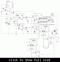
can i modify this and use with 230V AC input ?

**broken link removed**
 

You can, but it would need a decent amount of modifications. And to do those modifications, you should first acquire enough knowledge. eg. The MOSFETs - you would need to use 900V MOSFETs. You would need an input rectifier and filter stage, an auxiliary power supply, isolated feedback circuitry, etc.
 

ok ,can i modify a computer SMPS to -40V 0v +40V / 10A ?
 

Probably not. You can only do it if the computer power supply is very powerful. Regular ATX power supplies can't handle it. You're requiring about 800W of power. So, you're better off making your own circuit or buying a ready made power supply rated at +/-40V 10A.
 

For begining there is sense to try to do PSU without stabilization, possible amplifier will work quite well without it. Certainly else necessary to screw on filters and rectifiers to this scheme , but this is uncomplicated.
 
how to get a design for my requirement ?

thanks in advance
 

thanks DeepOne.

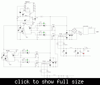
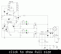
i have some doubts in this circuit...
1, can i replace IR2153 with SG3525 ?
2, where is the power supply source of IR2153 ?
3, is there any feedback system for voltage stabilization/ short circuit protection ?
4, output Ampere rating of this circuit ?
5, figure shows two +40v separate power supply, can i achieve -40V by rectifier diode reversing ?

thanks in advance
 

5, figure shows two +40v separate power supply, can i achieve -40V by rectifier diode reversing ?
The two 40V outputs are floating, so they can be connected in series with the center point connected to earth....
 
can i replace IR2153 with SG3525 ?
this is a different microcircuits and accordingly its schemes will be different.
where is the power supply source of IR2153 ?
power supply source of IR2153 is DC-DC based on Viper. Very reliable, in my observations.
is there any feedback system for voltage stabilization/ short circuit protection ?
No, but short circuit protection is reached by the half-bridge capacitors. Some voltage stabilization possible exists by the offset of the voltage on their common point. Аnd due to square-wave signal form in transformer voltage not in such degree depends from loads and capacity of output capacitors as in the event of with sinewave signal. Also, the absence of pwm modulation relieves output current filtering.
output Ampere rating of this circuit ?
40V 10A; - circuit pulls without problems, possible get even 40V 100А from one ir2153 if contribute small change in scheme and use IGBT.
 
Last edited:
thanks to DeepOne and godfreyl.

please clarify the transformer specification. Turns,core materiel,winding ...
 

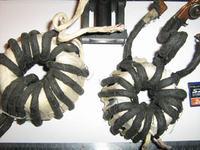
I usually use that under hand, and this most often is ring cores from faulty АС-AC converters from halogen lamps. For instance possible take ring from 300W converter. Correlation of turns for them looks as 40:13:13. For deflecting system core from CRT TV usually this will looks as 26:7:7.
 

@deep one. can you upload the pictures of Toroidal core and gauge of primary and secondary winding.
 

can you upload the pictures
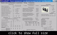
Yes, but better if you select core by themselves. This easy realize with the help of program "Excelent IT v5" (i think possible there are also other similar programs).
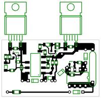
**broken link removed**
For instance ETD 49 core without air gap will fit fine.
Interface in russian language there but if it is necessary i can help with translation.

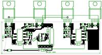
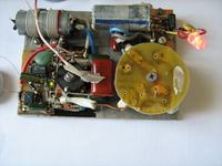
Another circuit, pwm stabilized, P<2kW
 
Last edited:
Hello
greetings can ETD59 be used for this schematic with IGBTs to get more power please can anyone help me to calculate turn ratios of etd 59
nice project to make
warm regards
andrew lebon
 

Status
Not open for further replies.

Similar threads

Part and Inventory Search

Welcome to EDABoard.com

Sponsor

Back
Top