Continue to Site

Welcome to EDAboard.com

Welcome to our site! EDAboard.com is an international Electronics Discussion Forum focused on EDA software, circuits, schematics, books, theory, papers, asic, pld, 8051, DSP, Network, RF, Analog Design, PCB, Service Manuals... and a whole lot more! To participate you need to register. Registration is free. Click here to register now.

2 MHz Band Stop Filter with High attenuation coefficient

Status
Not open for further replies.

arsalanarm

Junior Member level 3
Joined
Sep 1, 2012
Messages
30
Helped
0
Reputation
0
Reaction score
0
Trophy points
1,286
Activity points
1,676
Hi all
i need a band stop filter With the following specifications:

Center frequency :2 MHz

Pass Band Width : 1MHz

High attenuation coefficient

" i need to Completely Remove 1MHz To 3MHz Frequency"


please help to Design this Filter or Put The Related Schematic or Datasheet

Thank you Very much
 

You can't "Completely remove" a signal with a filter. How much attenuation of the signal do you need?
 

Center frequency :2 MHz
Pass Band Width : 1MHz
High attenuation coefficient
" i need to Completely Remove 1MHz To 3MHz Frequency"

"Remove" 1...3 MHz with a passband of 1 MHz around the center of 2 MHz. Sounds a bit problematic ?
 

Hi Again
i need Maximum possible attenuation.
If the filter is not necessary This function can be realized By any other circuit.
I Design and Test a passive 3st Order Band Stop Butterworth Filter with following Specification
Center frequency :2 MHz
Pass Band Width : 1MHz
but its attenuation coefficient is low (about 50 percent) i need a circuit with Maximum possible attenuation (filter or other circuits).
please Help To solve this problem Thank you Very Much
Arsalanarm.
 

WHen you define a narrow band stop filter you define its 3dB bw and its's center f/bw=Q factor.

But you have a Q of 2 which is very poor. For this reason you need to define more points of bandstop to realize this filter since it must be a much higher order than 2.
Start with the bandpass characterisitics and then the band stop rejection at several points and then the reason why you need this.

Eg. Loss at 0.9MHz, 1.1MHz 1.5 , 2, 2.5 ,2.9MHz, 3.1 MHz
 

Can be used multiple passive Filter Together?
Do not Have Effect on Other?or i must be use the Active Filter?
 

Can be used multiple passive Filter Together?
Do not Have Effect on Other?or i must be use the Active Filter?

arsalanarm, at first we need a clear specification (attenuation requirements) - as mentioned by SunnySkyguy already.

You mention in post#4 a "pass band width" of 1 MHz. I suppose you mean instead "stop band width", don't you?
You speak about "maximum possible attenuation" - this means nothing!
You must specify required attenuation values for at least 3 frequencies: center frequency and two other frequencies equivalent to the required stop band.
Only then the order of the transfer function can be fixed.
 

Can be used multiple passive Filter Together?
Do not Have Effect on Other?or i must be use the Active Filter?
Of course passive filters interact. Also active filters do in so far, that in the overall characteristic the specification of one filter is dwarted by the other. So you'll basically want to specify the overall filter characteristic and chose a suitable filter topology.

As you already found out, it's imposible to prescribe a certain filter prototype (e.g. third order butterworth) and expect an arbitrary filter characteristic at the same time. The usual way is to specify the filter characteristic by a rectangular pass- and stopband mask.

You didn't yet tell quantitative parameters, but I guess the requirements will end up in a higher order filter with zeros, e.g. a Chebyshev II or elliptic (Cauer) filter. They can be designed with specified stop band attenuation.

Alternatively, an active low-pass/high-pass parallel circuit would be easy to design.

I suppose you mean instead "stop band width", don't you?
I suppose, too. Curiously, Nuhertz Filter Solutions is also asking for "Pass Band Width" instead of "Stop Band Width" for a bandstop filter.
 
Last edited:

i need a Blok With the following specifications:

input signal frequency :0 to 6 MHz

output signal Frequency : 0 to 1MHz + High Weakened signal 1MHz To 3MHz Signal + 3 to 6MHz

" ideally i need to Completely Remove 1MHz To 3MHz Frequency"

Thank you Very much again

- - - Updated - - -

To clarify the issue

i need a Block With the following specifications:

input signal frequency :0 to 6 MHz

output signal Frequency : 0 to 1MHz + Very Weakened signal 1MHz To 3MHz Signal + 3 to 6MHz

" ideally i need to Completely Remove 1MHz To 3MHz Frequency"

Thank you Very much again
 

To clarify the issue
i need a Block With the following specifications:
input signal frequency :0 to 6 MHz
output signal Frequency : 0 to 1MHz + Very Weakened signal 1MHz To 3MHz Signal + 3 to 6MHz
" ideally i need to Completely Remove 1MHz To 3MHz Frequency"
Thank you Very much again

Ok, as far as I could understand your "specification" you need a brickwall lowpass which has a pass band from 0 to 1 MHz and then sharply goes down to zero.
Is this correct?
In this case, I must tell you - it is impossible.
As mentioned already several times - you must specify frequencies with corresponding maximum allowable levels. We live in a real world - and nothing is ideal.
 

What is the input and output impedance for the filter?
 

Your latest post isn't but another way to say that you can't (or don't want to) give a quantitative filter specification, as required for a real design.

We already heard that "completely remove" means considerably more attenuation than 50 % (we usually say -6 dB), almost expectable.

I see two ways to approach a serious specification:
- take a closer look at the usual way to specify a filter by pass- and stopband parameters.
- forget about quantitative specifications for a while and describe the application problem. Make us understand your requirements.

For the first way, I presume the standard -3 dB passband limits can work. In addition, we'll need the transition band width for both sides, and the minimum stop band attenuation.

- - - Updated - - -

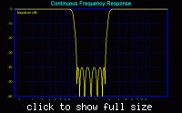
P.S.: If you are able to give a feasible specification, it may end up in something like below. The circuit effort would be unconveniently high.

 
Last edited:

Judging by the user's other posts, he is looking for a video cam signal filter somewhere.

For powering the camera, you need a clean supply source from DC to 5MHz. This means you need to block all frequencies. Usually this is done with a ferrite bead or small inductor and 2 good caps like 22uF and 0.1uF. Low ESR caps are better with short leads or SMD. Powering a camera chip needs caps directly near the camera. Video signals are easily routed between DVD VCR and TV because they use 75 Ohm source and loads with a 75 ohm coaxial cable.

Ground is not 0V for RF unless it is not inductive on a large ground plane. Without this you need to router ground paths so that no high current levels get conducted, induced or otherwise added on your video ground circuit reference point.


If you follow these methods and still get video noise, let us know what you tried and what you see.

PLease understand that you need to be careful with ground connections so that they are non-inductive between interfaces (braid is better than a thin wire , coax is better than an thin wire good low ESR Caps and small ceramic caps to shunt noise dropped on series power line inductance. If there are large pulsed relays , switchers or H bridges near the video signal a common mode filter is recommend using clam-shell choke, just like the one on every VGA video cable.
 

Video application sounds plausible, but unlikely a simple supply block.
 

Status
Not open for further replies.

Similar threads

Part and Inventory Search

Welcome to EDABoard.com

Sponsor

Back
Top